
Datasheet


LT1073
6
APPLICATIO S I FOR ATIO
WUUU
Measuring Input Current at Zero or Light Load
Obtaining meaningful numbers for quiescent current and
efficiency at low output current involves understanding
how the LT1073 operates. At very low or zero load current,
the device is idling for seconds at a time. When the output
voltage falls enough to trip the comparator, the power
switch comes on for a few cycles until the output voltage
rises sufficiently to overcome the comparator hysteresis.
When the power switch is on, inductor current builds up
to hundreds of milliamperes. Ordinary digital multimeters
are not capable of measuring average current because of
bandwidth and dynamic range limitations. A different
approach is required to measure the 100µA off-state and
500mA on-state currents of the circuit.
Table 1. Component Selection for Step-Up Converters
INPUT BATTERY OUTPUT OUTPUT INDUCTOR INDUCTOR CAPACITOR
VOLTAGE (V) TYPE VOLTAGE (V) CURRENT (MIN) VALUE (µH) PART NUMBER VALUE (µF) NOTES
1.55-1.25 Single Alkaline 3 60mA 82 G GA10-822K, CB 7300-12 150
1.30-1.05 Single Ni-Cad 3 20mA 180 G GA10-183K, CB 7300-16 47
1.55-1.25 Single Alkaline 5 30mA 82 G GA10-822K, CB 7300-12 100
1.30-1.05 Single Ni-Cad 5 10mA 180 G GA10-183K, CB 7300-16 22
3.1-2.1 Two Alkaline 5 80mA 120 G GA10-123K, CB 7300-14 470 *
3.1-2.1 Two Alkaline 5 25mA 470 G GA10-473K, CB 7300-21 150 *
3.3-2.5 Lithium 5 100mA 150 G GA40-153K, CB 6860-15 470 *
3.1-2.1 Two Alkaline 12 25mA 120 G GA10-123K, CB 7300-14 220
3.1-2.1 Two Alkaline 12 5mA 470 G GA10-473K, CB 7300-21 100
3.3-2.5 Lithium 12 30mA 150 G GA10-153K, CB 7300-15 220
4.5-5.5 TTL Supply 12 90mA 220 G GA40-223K, CB 6860-17 470 *
4.5-5.5 TTL Supply 12 22mA 1000 G GA10-104K, CB 7300-25 100 *
4.5-5.5 TTL Supply 24 35mA 220 G GA40-223K, CB 6860-17 150 *
G = GOWANDA CB = CADDELL-BURNS *Add 68Ω from I
LIM
to V
IN
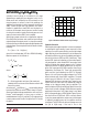
LT1073. The circuit must be “booted” by shorting V2 to
V
SET
. After the LT1073 output voltage has settled, discon-
nect the short. Input voltage is V2 and average input
current can be calculated by this formula:
I
VV
IN
=
Ω
21
100
–
Inductor Selection
A DC/DC converter operates by storing energy as mag-
netic flux, in an inductor core and then switching this
energy into the load. Since it is flux, not charge, that is
stored, the output voltage can be higher, lower, or oppo-
site in polarity to the input voltage by choosing an appro-
priate switching topology. To operate as an efficient energy
transfer element, the inductor must fulfill three require-
ments. First, the inductance must be low enough for the
inductor to store adequate energy under the worst-case
condition of minimum input voltage and switch ON time.
The inductance must also be high enough so that maxi-
mum current ratings of the LT1073 and inductor are not
exceeded at the other worst-case condition of maximum
input voltage and ON time. Additionally, the inductor core
must be able to store the required flux, i.e., it must not
saturate. At power levels generally encountered with
LT1073-based designs, small axial-lead units with
Figure 1. Test Circuit Measures No-Load
Quiescent Current of LT1073 Converter
–
+
1073 F01
LTC1050
LT1073
CIRCUIT
+
12V
1MΩ
100Ω
V
SET
1000µF
1µF*
*NONPOLARIZED
V1 V2
Quiescent current can be accurately measured using the
circuit in Figure 1. V
SET
is set to the input voltage of the