
Datasheet


LT1073
7
saturation current ratings in the 300mA to 1A range
(depending on application) are adequate. Lastly, the in-
ductor must have sufficiently low DC resistance so that
excessive power is not lost as heat in the windings. An
additional consideration is electro-magnetic interference
(EMI). Toroid and pot core type inductors are recom-
mended in applications where EMI must be kept to a
minimum; for example, where there are sensitive analog
circuitry or transducers nearby. Rod core types are a less
expensive choice where EMI is not a problem.
Specifying a proper inductor for an application requires
first establishing minimum and maximum input voltage,
output voltage and output current. In a step-up converter,
the inductive events add to the input voltage to produce the
output voltage. Power required from the inductor is deter-
mined by:
P
L
= (V
OUT
+ V
D
– V
IN
)(I
OUT
)
where V
D
is the diode drop (0.5V for a 1N5818 Schottky).
Maximum power in the inductor is
PEf
Li f
L L OSC
PEAK OSC
=
=
•
•
1
2
2
where
i
V
R
e
Rt
L
PEAK
IN ON
=
1–
–
R = Switch equivalent resistance (1Ω maximum)
added to the DC resistance of the inductor and t
ON
= ON
time of the switch.
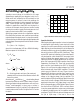
At maximum V
IN
and ON time, i
PEAK
should not be allowed
to exceed the maximum switch current shown in Figure 2.
Some input/output voltage combinations will cause con-
tinuous
1
mode operation. In these cases a resistor is
needed between I
LIM
(Pin 1) and V
IN
(Pin 2) to keep switch
current under control. See the “Using the I
LIM
Pin” section
for details.
Capacitor Selection
Selecting the right output capacitor is almost as important
as selecting the right inductor. A poor choice for a filter
capacitor can result in poor efficiency and/or high output
ripple. Ordinary aluminum electrolytics, while inexpensive
and readily available, may have unacceptably poor equiva-
lent series resistance (ESR) and ESL (inductance). There
are low-ESR aluminum capacitors on the market specifi-
cally designed for switch-mode DC/DC converters which
work much better than general purpose units. Tantalum
capacitors provide still better performance at more ex-
pense. We recommend OS-CON capacitors from Sanyo
Corporation (San Diego, CA). These units are physically
quite small and have extremely low ESR. To illustrate,
Figures 3, 4, and 5 show the output voltage of an LT1073
based converter with three 100µF capacitors. The peak
switch current is 500mA in all cases. Figure 3 shows a
Sprague 501D aluminum capacitor. V
OUT
jumps by over
150mV when the switch turns off, followed by a drop in
voltage as the inductor dumps into the capacitor. This
works out to be an ESR of over 300mΩ. Figure 4 shows the
same circuit, but with a Sprague 150D tantalum capacitor
replacing the aluminum unit. Output jump is now about
30mV, corresponding to an ESR of 60mΩ. Figure 5 shows
the circuit with an OS-CON unit. ESR is now only 30mΩ.
In very low power applications where every microampere
is important, leakage current of the capacitor must be
considered. The OS-CON units do have leakage current in
the 5µA to 10µA range. If the load is also in the
APPLICATIO S I FOR ATIO
WUUU
V
IN
(V)
0
I
SWITCH
(mA)
1200
1000
800
600
400
200
0
1234
1073 F02
5
Figure 2. Maximum Switch Current vs Input Voltage
NOTE 1:
i.e., inductor current does not go to zero when the switch is off.