
Datasheet


7
LT1080/LT1081
10801fe
APPLICATIO S I FOR ATIO
WUU
U
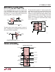
When driving CMOS logic from a receiver that will be used
in the SHUTDOWN mode and there is no other active
receiver on the line, a 51k resistor can be placed from the
logic input to V
CC
to force a definite logic level when the
receiver output is in a high impedance state.
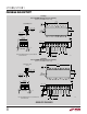
The generated driver supplies (V
+
and V
–
) may be used to
power external circuitry such as other RS232 drivers or op
amps. They should be loaded with care, since excessive
loading can cause the generated supply voltages to drop,
causing the RS232 driver output voltages to fall below
RS232 requirements. See the graph “Supply Generator
Outputs” for a comparison of generated supply voltage
versus supply current.
1080/81 F08
DRIVER
V
+
3
EXTERNAL OP AMP
LT1080
V
–
V
+
V
–
7
1µF
1µF
–
+
GND
16
+
TYPICAL APPLICATIO
U
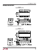
To protect against receiver input overloads in excess of
±30V, a voltage clamp can be placed on the data line and
still maintain RS232 compatibility.
RS232
INPUT
RECEIVER
LOGIC
OUTPUT
1080/81 F067
5k
1k*
30V
30V
* A PTC THERMISTOR WILL ALLOW
CONTINUOUS OVERLOAD OF GREATER THAN ±100V
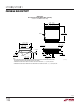
Operating with 5V and 12V
LOGIC
INPUTS
LOGIC
OUTPUTS
ON/OFF
18
10
13
11
12
6
5
4
2
16
9
14
8
15
7
3
17
5V INPUT12V INPUT*
–12V OUTPUT
RS232 OUTPUT
RS232 OUTPUT
RS232 INPUT
RS232 INPUT
1080/81 • TA03
5k
5k
LT1080
1µF
1µF
* PIN 1 USED ON LT1081.
1080/81 F06
RS232
INPUT
ON/OFF
INPUT
LT1080
RECEIVER
CMOS
LOGIC
LOGIC
OUTPUT
V
CC
51k*
* FORCES LOGIC INPUT STATE WHEN V
ON/OFF
IS LOW