
Datasheet


8
LT1083/84/85 Fixed
APPLICATIONS INFORMATION
WUU
U
voltage is rising, the input-to-output voltage differential
remains small allowing the regulator to supply large
output currents. With high input voltage a problem can
occur wherein removal of an output short will not allow the
output voltage to recover. Older regulators such as the
7800 series, also exhibited this phenomenon so it is not
unique to the LT1083.
The problem occurs with a heavy output load when the
input voltage is high and the output voltage is low, such as
immediately after a removal of a short. The load line for
such a load may intersect the output current curve at two
points. If this happens there are two stable output operat-
ing points for the regulator. With this double intersection
the power supply may need to be cycled down to zero and
brought up again to make the output recover.
Ripple Rejection
In applications that require improved ripple rejection the
LT1083 series adjustable regulators should be used. With
LT1083 series adjustable regulators the addition of a
bypass capacitor from the adjust pin to ground will reduce
output ripple by the ratio of V
OUT
/1.25V. See LT1083
series adjustable regulator data sheet.
Load Regulation
Because the LT1083 is a three-terminal device, it is not
possible to provide true remote load sensing. Load regu-
lation will not be limited by the resistance of the wire
connecting the regulator to the load. The data sheet
specification for the load regulation is measured at the
bottom of the package. Negative side sensing is a true
Kelvin connection, with the ground pin of the device
returned to the negative side of the load.
Thermal Considerations
The LT1083 series of regulators have internal power and
thermal limiting circuitry designed to protect the device
under overload conditions. For continuous normal load
conditions however, maximum junction temperature rat-
ings must not be exceeded. It is important to give careful
consideration to all sources of thermal resistance from
junction to ambient. This includes junction-to-case, case-
to-heat sink interface, and heat sink resistance itself. New
output voltage increases. This negative resistance can
react with capacitors or inductors on the input to cause
oscillations during current limiting. Depending on the
value of series resistance, the overall circuitry may end up
unstable. Since this is a system problem, it is not neces-
sarily easy to solve; however it does not cause any prob-
lems with the IC regulator and can usually be ignored.
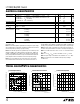
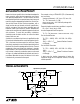
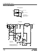
Protection Diodes
In normal operation the LT1083 family does not need any
protection diodes, The internal diode between the input
and the output pins of the LT1083 family can handle
microsecond surge currents of 50A to 100A. Even with
large output capacitances it is very difficult to get those
values of surge current in normal operation. Only with high
value output capacitors, such as 1000µF to 5000µF and
with the input pin instantaneously shorted to ground, can
damage occur. A crowbar circuit at the input of the LT1083
can generate those kinds of currents and a diode from
output-to-input is then recommended. Normal power sup-
ply cycling or even plugging and unplugging in the system
will not generate currents large enough to do any damage.
V
IN
V
OUT
LT1083
ADJ
IN OUT
LT1083/4/5 AI01
C
OUT
150µF
+
D1
1N4002
(OPTIONAL)
Overload Recovery
Like any of the IC power regulators, the LT1083 has safe
area protection. The safe area protection decreases the
current limit as input-to-output voltage increases and
keeps the power transistor inside a safe operating region
for all values of input-to-output voltage. The LT1083
protection is designed to provide some output current at
all values of input-to-output voltage up to the device
breakdown.
When power is first turned on, as the input voltage rises,
the output follows the input, allowing the regulator to start
up into very heavy loads. During the start-up, as the input