
Datasheet


9
LT1083/84/85 Fixed
thermal resistance specifications have been developed to
more accurately reflect device temperature and ensure
safe operating temperatures. The data section for these
new regulators provides a separate thermal resistance and
maximum junction temperature for both the
Control Sec-
tion
and the
Power Section
. Previous regulators, with a
single junction-to-case thermal resistance specification,
used an average of the two values provided here and
therefore could allow excessive junction temperatures
under certain conditions of ambient temperature and heat
sink resistance. To avoid this possibility, calculations
should be made for both sections to ensure that both
thermal limits are met.
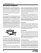
Junction-to-case thermal resistance is specified from the
IC junction to the bottom of the case directly below the die.
This is the lowest resistance path for heat flow. Proper
mounting is required to ensure the best possible thermal
flow from this area of the package to the heat sink. Thermal
compound at the case-to-heat sink interface is strongly
recommended. If the case of the device must be electroni-
cally isolated, a thermally conductive spacer can be used
as long as its added contribution to thermal resistance is
considered. Note that the case of all devices in this series
is electronically connected to the ouput.
For example, using a LT1083-5CK (TO-3, Commercial)
and assuming:
V
IN
(max continuous) = 9V, V
OUT
= 5V, I
OUT
= 6A,
T
A
= 75°C θ
HEAT SINK
= 1°C/W,
θ
CASE-TO-HEAT SINK
= 0.2°C/W for K package with
thermal compound.
Power dissipation under these conditions is equal to:
P
D
= (V
IN
– V
OUT
) (I
OUT
) = 24W
Junction temperature will be equal to:
T
J
= T
A
+ P
D
(θ
HEAT SINK
+ θ
CASE-TO-HEAT SINK
+ θ
JC
)
For the Control Section:
T
J
= 75°C + 24W (1°C/W + 0.2°C/W + 0.6°C/W) =
118°C
118°C < 125°C = T
JMAX
(Control Section Commer-
cial Range)
For the Power Transistor:
T
J
= 75°C + 24W (1°C/W + 0.2°C/W + 1.6°C/W) =
142°C
142°C < 150°C = T
JMAX
(Power Transistor Commer-
cial Range)
In both cases the junction temperature is below the
maximum rating for the respective sections, ensuring
reliable operation.
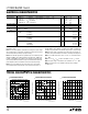
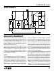
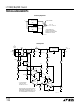
APPLICATIONS INFORMATION
WUU
U
High Efficiency Regulator
+
–
+
28V
INPUT
28V
470Ω
28V
4N28
1N914
1N914
LT1011
10k
10k
10k
1k
1M
MR1122
1mH
10,000µF
OUTPUT
LT1083-5 OUTIN
GND
LT1083/4/5 TA03
TYPICAL APPLICATIONS
U