
Datasheet


6
LT1118/LT1118-2.5
LT1118-2.85/LT1118-5
1118fc
thermally connected to the die substrate. Table 1 shows
measured thermal resistance from junction to ambient for
the LT1118 connected to various sized PC board ground
planes. The power dissipated in the LT1118 varies with
input voltage and loading. When the regulator is sourcing
current the power which must be dissipated by the pack-
age is:
P
D
= (V
IN
– V
OUT
) • I
LOAD
.
When the regulator is sinking load current, power dissipa-
tion is nearly independent of V
IN
and can be calculated as:
P
D
= V
OUT
• I
LOAD
.
Heat sinking to the IC package must consider the worst
case power dissipation which may occur.
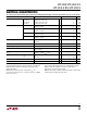
Table 1. Measured Thermal Resistance from Junction to
Ambient for the LT1118
S8 Package SOT-223
Free Air 120°C/W 95°C/W
1 Sq Inch Copper 55°C/W 53°C/W
4 Sq Inch Copper 35°C/W 38°C/W
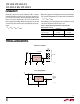
LT1118-2.85
GND
IN
27 LINES
2.2µF
5V
1µF
110Ω
110Ω
1118 TA03
110Ω
110Ω
110Ω
TERMPWR
OUT
•
•
•
•
•
•
•
•
+
LT1118-2.5
GND
IN
1µF
1118 TA04
5V
ANALOG
COMMON
2.5V
V
IN
5V
OUT
1µF
SCSI Active Terminator
Power Supply Splitter
OPERATIO
U
TYPICAL APPLICATIO S
U