
Datasheet


LT1158
1
1158fb
TYPICAL APPLICATION
DESCRIPTION
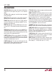
Half Bridge N-Channel
Power MOSFET Driver
A single input pin on the LT
®
1158 synchronously controls
two N-channel power MOSFETs in a totem pole confi gura-
tion. Unique adaptive protection against shoot-through
currents eliminates all matching requirements for the two
MOSFETs. This greatly eases the design of high effi ciency
motor control and switching regulator systems.
A continuous current limit loop in the LT1158 regulates
short-circuit current in the top power MOSFET. Higher
start-up currents are allowed as long as the MOSFET V
DS
does not exceed 1.2V. By returning the FAULT output to
the enable input, the LT1158 will automatically shut down
in the event of a fault and retry when an internal pull-up
current has recharged the enable capacitor.
An on-chip charge pump is switched in when needed to
turn on the top N-channel MOSFET continuously. Special
circuitry ensures that the top side gate drive is safely
maintained in the transition between PWM and DC opera-
tion. The gate-to-source voltages are internally limited to
14.5V when operating at higher supply voltages.
L, LT, LTC and LTM are registered trademarks of Linear Technology Corporation. All other
trademarks are the property of their respective owners. Protected by U.S. Patents including
5365118.
Top and Bottom Gate Waveforms
FEATURES
APPLICATIONS
n
Drives Gate of Top Side MOSFET Above V
+
n
Operates at Supply Voltages from 5V to 30V
n
150ns Transition Times Driving 3000pF
n
Over 500mA Peak Driver Current
n
Adaptive Non-Overlap Gate Drives
n
Continuous Current Limit Protection
n
Auto Shutdown and Retry Capability
n
Internal Charge Pump for DC Operation
n
Built-In Gate Voltage Protection
n
Compatible with Current-Sensing MOSFETs
n
TTL/CMOS Input Levels
n
Fault Output Indication
n
PWM of High Current Inductive Loads
n
Half Bridge and Full Bridge Motor Control
n
Synchronous Step-Down Switching Regulators
n
Three-Phase Brushless Motor Drive
n
High Current Transducer Drivers
n
Battery-Operated Logic-Level MOSFETs
+
–
R
SENSE
0.015Ω
500μF
LOW
ESR
0.1μF
IRFZ34
IRFZ34
24V
1N4148
10μF
1μF
0.01μF
PWM
0Hz TO
100kHz
BOOST
BOOST DR
T GATE DR
T GATE FB
T SOURCE
SENSE
+
SENSE
–
B GATE DR
B GATE FB
GND
V
+
V
+
INPUT
ENABLE
FAULT
BIAS
LT1158
LOAD
LT1158 TA01
+
+
+
V
IN
= 24V
R
L
= 12Ω
1158 TA02