
Datasheet


LT1158
13
1158fb
APPLICATIONS INFORMATION
Low Current Shutdown
The LT1158 may be shutdown to a current level of 2mA by
pulling the enable pin 4 low. In this state both the top and
bottom MOSFETs are actively held off against any transients
which might occur on the output during shutdown. This
is important in applications such as 3-phase DC motor
control when one of the phases is disabled while the other
two are switching.
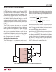
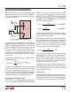
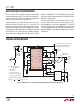
If zero standby current is required and the load returns to
ground, then a switch can be inserted into the supply path
of the LT1158 as shown in Figure 5. Resistor R
GS
ensures
that the top MOSFET gate discharges, while the voltage
across the bottom MOSFET goes to zero. The voltage drop
across the P-channel supply switch must be less than
300mV, and R
GS
must be 330k or greater for DC operation.
This technique is not recommended for applications which
require the LT1158 V
DS
sensing function.
Figure 5. Adding Zero Current Shutdown
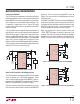
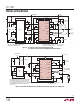
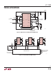
Figure 7. Short-Circuit Protection with Current-Sensing MOSFET
Figure 6. Short-Circuit Protection with Standard MOSFET
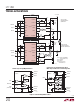
Short-Circuit Protection in Bridge Applications
The LT1158 protects the top power MOSFET from output
shorts to ground, or in a full bridge application, shorts
across the load. Both standard 3-lead MOSFETs and cur-
rent-sensing 5-lead MOSFETs can be protected. The bottom
MOSFET is not protected from shorts to supply.
Current is sensed by measuring the voltage across a cur-
rent shunt in the source lead of a standard 3-lead MOSFET
(Figure 6). For the current-sensing MOSFET shown in
Figure 7, the sense resistor is inserted between the sense
and Kelvin leads.
The SENSE
+
and SENSE
–
PC traces must be routed together
at minimum spacing to prevent stray pickup, and a Kelvin
connection must be used at the current shunt for the 3-lead
MOSFET. Using a twisted pair is the safest approach and
is recommended for sense runs of several inches.
When the voltage across R
SENSE
exceeds 110mV, the
LT1158 FAULT pin begins to conduct, signaling a fault
condition. The current in a short circuit ramps very rapidly,
limited only by the series inductance and ultimately the
MOSFET and shunt resistance. Due to the response time
100k
V
+
V
+
LT1158
VP0300
R
GS
1158 F05
LOAD
GND
TO OTHER
CONTROL
CIRCUITS
CMOS
ON/OFF
100k
V
+
T GATE DR
T GATE FB
T SOURCE
B GATE DR
B GATE FB
2N2222
+
+
T GATE DR
T GATE FB
T SOURCE
SENSE
+
SENSE
–
FAULT
LT1158
R
SENSE
5V
V
+
1158 F06
10k
+
T GATE DR
T GATE FB
T SOURCE
SENSE
+
SENSE
–
FAULT
LT1158
5V
V
+
1158 F07
10k
R
SENSE
KELVIN
SENSE
OUTPUT
+