
Datasheet


LT1158
14
1158fb
APPLICATIONS INFORMATION
the value of R
SENSE
for the 5-lead MOSFET increases by
the current sensing ratio (typically 1000 – 3000), thus
eliminating the need for a low valued shunt. ΔV is in the
range of 1V to 3V in most applications.
Assuming a dead short, the MOSFET dissipation will rise
to V
SUPPLY
• I
SC
. For example, with a 24V supply and I
SC
= 10A, the dissipation would be 240W. To determine how
long the MOSFET can remain at this dissipation level before
it must be shut down, refer to the SOA curves given in
the MOSFET data sheet. For example, an IRFZ34 would
be safe if shut down within 10ms.
A Tektronix A6303 current probe is highly recommended
for viewing output fault currents.
If Short-Circuit Protection is Not Required
In applications which do not require the current sense
capability of the LT1158, the sense pins 11 and 12 should
both be connected to pin 13, and the FAULT pin 5 left
open. The enable pin 4 may still be used to shut down
the device. Note, however, that when unprotected the top
MOSFET can be easily (and often dramatically) destroyed
by even a momentary short.
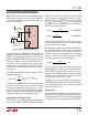
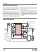
Self-Protection with Automatic Restart
When using the current sense circuits of Figures 6 and 7,
local shutdown can be achieved by connecting the FAULT
pin through resistor R
F
to the enable pin as shown in
Figure 9. An optional thermostat mounted to the load or
MOSFET heatsink can also be used to pull enable low.
An internal 25μA current source normally keeps the enable
capacitor CEN charged to the 7.5V clamp voltage (or to V
+
,
for V
+
< 7.5V). When a fault occurs, CEN is discharged to
below the enable low threshold (1.15V typ) which shuts
down both MOSFETs. When the FAULT pin or thermostat
releases, CEN recharges to the upper enable threshold
where restart is attempted. In a sustained short circuit,
FAULT will again pull low and the cycle will repeat until the
short is removed. The time to shut down for a DC input
or thermal fault is given by:
t
SHUTDOWN
= (100 + 0.8R
F
) C
EN
DC input
of the LT1158 current limit loop, an initial current spike of
from 2 to 5 times the fi nal value will be present for a few
μs, followed by an interval in which I
DS
= 0. The current
spike is normally well within the safe operating area (SOA)
of the MOSFET, but can be further reduced with a small
(0.5μH) inductor in series with the output.
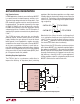
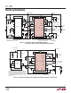
Figure 8. Top MOSFET Short-Circuit Turn-On current
5μs/DIV
LT1158 F08
5A/DIV
I
SC
If neither the enable nor input pins are pulled low in
response to the fault indication, the top MOSFET current
will recover to a steady-state value I
SC
regulated by the
LT1158 as shown in Figure 8:
I
SC
=
=
=
()
150mV
R
R
150mV
I
I
r 150mV
R
SENSE
SENSE
SC
SC
SSENSE
2
SENSE
SC
1
150mV
V
R
r 150mV
I
1
−
⎛
⎝
⎜
⎞
⎠
⎟
=
()
−
−
Δ
1150mV
V
sense ratio, V = V
2
Δ
Δ
⎛
⎝
⎜
⎞
⎠
⎟
=
−
r current
GGS
=−VV
GS T
The time for the current to recover to I
SC
following the
initial current spike is approximately Q
GS
/0.5mA, where
Q
GS
is the MOSFET gate-to-source charge. I
SC
need not
be set higher than the required start-up current for mo-
tors (see Starting High In-Rush Current Loads). Note that