
Datasheet


LT1175
9
1175ff
APPLICATIONS INFORMATION
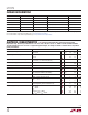
Setting Output Voltage
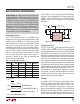
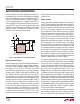
The LT1175 adjustable version has a feedback sense
voltage of 3.8V with a bias current of approximately 75nA
fl owing out of the SENSE pin. To avoid output voltage
errors caused by this current, the output divider string
(see Figure 1) should draw about 25μA. Table 1 shows
suggested resistor values for a range of output voltages.
The second part of the table shows resistor values which
draw only 10μA of current. Output voltage error caused
by bias current with the lower valued resistors is about
0.4% maximum and with the higher values, about 1%
maximum. A formula is also shown for calculating the
resistors for any output voltage.
Table 1. Suggested Divider Resistors
OUTPUT
VOLTAGE
R1
I
DIV
= 25μA
R2
NEAREST 1%
R1
I
DIV
= 10μA
R2
NEAREST 1%
5V 150k 47.5k 383k 121k
6V 150k 86.6k 383k 221k
8V 150k 165k 383k 422k
10V 150k 243k 383k 619k
12V 150k 324k 383k 825k
15V 150k 442k 383k 1.13M
R
V
I
R
RV V
V
Simple formula
RV V
VRI
I Desired
DIV
OUT
OUT
FB
DIV
1
38
2
138
38
138
38 1
=
=
−
()
()
=
−
()
+
()
⎛
⎝
⎜
⎞
⎠
⎟
=
.
.
.
.
.
R2
Taking SENSE pin bias
current into account
divider current
Note to Reader: To avoid confusion when working with
negative voltages (is –6V more or less than –5V?), I have
decided to treat the LT1175 as if it were a positive regulator
and express all voltages as positive values, both in text and
in formulas. If you do the same and simply add a negative
sign to the eventual answer, confusion should be avoided.
Please don’t give me a hard time about “preciseness” or
“correctness.” I have to fi eld phone calls from around
the world and this is my way of dealing with a multitude
of conventions. Thanks for your patience.
The LT1175-5 is a fi xed 5V design with the SENSE pin
acting as a Kelvin connection to the output. Normally the
SENSE pin and the OUTPUT pin are connected directly
together, either close to the regulator or at the remote
load point.
Setting Current Limit
The LT1175 uses two I
LIM
pins to set current limit (typical)
at 200mA, 400mA, 600mA or 800mA. The corresponding
minimum guaranteed currents are 130mA, 260mA, 390mA
and 520mA. This allows the user to select a current limit
tailored to his specifi c application and prevents the situa-
tion where short-circuit current is many times higher than
full-load current. Problems with input supply overload or
excessive power dissipation in a faulted load are prevented.
Power limiting in the form of foldback current limit is built
in and reduces current limit as a function of input-to-output
voltage differential for differentials exceed
ing 14V. See the
graph in Typical Performance Characteristics. The LT1175
is guaranteed to be blowout-proof regardless of current
limit setting. The power limiting combined with thermal
shutdown protects the device from destructive junction
temperatures under all load conditions.
Shutdown
In shutdown, the LT1175 draws only about 10μA. Special
circuitry is used to minimize increases in shutdown cur-
rent at high temperatures, but a slight increase is seen
above 125°C. One option not taken was to actively pull
down on the output during shutdown. This means that the
output will fall slowly after shutdown is initiated, at a rate
determined by load current plus the 12μA internal load,
and the size of the output capacitor. Active pull-down is
Figure 1. Typical LT1175 Adjustable Connection
+
C
IN
C
OUT
≥ 0.1μF
V
OUT
–12V
R2
825k
1%
R1
383k
1%
SHUTDOWN
LOGIC
SHDN GND
LT1175
SENSE
OUTPUT
> 2V OR < –2V TO
TURN REGULATOR ON
1175 F01
I
LIM4
I
LIM2
V
IN
+