
Datasheet


LT1175
12
1175ff
APPLICATIONS INFORMATION
capacitors do not fail during a “shorting out” surge, only
during a “charge up” surge.
The output capacitor should be located within several
inches of the regulator. If remote sensing is used, the output
capacitor can be located at the remote sense node, but the
GND pin of the regulator should also be connected to the
remote site. The basic rule is to keep SENSE and GND pins
close to the output capacitor, regardless of where it is.
Operating at very large input-to-output differential volt-
ages (>15V) with load currents less than 5mA requires an
output capacitor with an ESR greater than 1Ω to prevent
low level output oscillations.
Input Capacitor
The LT1175 requires a separate input bypass capacitor
only if the regulator is located more than six inches from
the raw supply output capacitor. A 1μF or larger tantalum
capacitor is suggested for all applications, but if low ESR
capacitors such as ceramic or fi lm are used for the out-
put and input capacitors, the input capacitor should be
at least three times the value of the output capacitor. If a
solid tantalum or aluminum electrolytic output capacitor
is used, the input capacitor is very noncritical.
High Temperature Operation
The LT1175 is a micropower design with only 45μA qui-
escent current. This could make it perform poorly at high
temperatures (>125°C), where power transistor leakage
might exceed the output node loading current (5μA to
15μA). To avoid a condition where the output voltage
drifts uncontrolled high during a high temperature no-load
condition, the LT1175 has an active load which turns on
when the output is pulled above the nominal regulated
voltage. This load absorbs power transistor leakage and
maintains good regulation. There is one downside to this
feature, however. If the output is pulled high deliberately, as
it might be when the LT1175 is used as a backup to a slightly
higher output from a primary regulator, the LT1175 will act
as an unwanted load on the primary regulator. Because of
this, the active pull-down is deliberately “weak.” It can be
modeled as a 2k resistor in series with an internal clamp
voltage when the regulator output is being pulled high. If
a 4.8V output is pulled to 5V, for instance, the load on the
primary regulator would be (5V – 4.8V)/2kΩ = 100μA.
This also means that if the internal pass transistor leaks
50μA, the output voltage will be (50μA)(2kΩ) = 100mV
high. This condition will not occur under normal operating
conditions, but could occur immediately after an output
short circuit had overheated the chip.
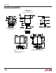
Thermal Considerations
The LT1175 is available in a special 8-pin surface mount
package which has Pins 1 and 8 connected to the die attach
paddle. This reduces thermal resistance when Pins 1 and 8
are connected to expanded copper lands on the PC board.
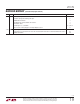
Table 2 shows thermal resistance for various combinations
of copper lands and backside or internal planes. Table 2
also shows thermal resistance for the 5-pin DD surface
mount package and the 8-pin DIP and package.
Table 2. Package Thermal Resistance (°C/W)
LAND AREA DIP ST SO Q
Minimum 140 90 100 60
Minimum with
Backplane
110 70 80 50
1cm
2
Top Plane with
Backplane
100 64 75 35
10cm
2
Top Plane
with Backplane
80 50 60 27
To calculate die temperature, maximum power dissipation
or maximum input voltage, use the following formulas
with correct thermal resistance numbers from Table 2.
For through-hole TO-220 applications use θ
JA
= 50°C/W
without a heat sink and θ
JA
= 5°C/W + heat sink thermal
resistance when using a heat sink.
Die V V I
Maximum
JA IN OUT LOAD
Temp=T +
A
θ−
()()
Power Dissipation =
T
MAX
− T
A
JA
θ
=
T
MAX
− T
AA
JA LOAD
OUT
I
V
θ
()
+
Maximum Input Voltage
for Thermal Considerations