
Datasheet


9
LT1185
1185ff
APPLICATIO S I FOR ATIO
WUUU
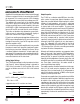
Figure 3. Shutdown Techniques
R
LIM
†
4k
+
–
V
IN
R6
30k
R7
2.4k
†
R1
R2
V
OUT
+
Q1
2N3906
*
LT1185 • F3a
*CMOS LOGIC
†
FOR HIGHER VALUES OF R
LIM
, MAKE R7 = (R
LIM
)(0.6)
5V
R5
300k
+
REF GND
FB
V
OUT
V
IN
LT1185
5V Logic, Positive Regulated Output
5V Logic, Negative Regulated Output
R
LIM
–
LT1185 • F03b
REF GND
FB
V
OUT
LT1185V
IN
R4
33k
5V
“HI” = OUTPUT “OFF”
3 EA 1N4148
V
IN
Q1
2N3906
for remote sense applications, they may need to be con-
sidered. Ground lead resistance of 0.4Ω would cause an
output voltage error of up to (3A/40)(0.4Ω) = 30mV, or
0.6% at V
OUT
= 5V. Note that if the sense leads are
connected as shown in Figure 2, with r
a
≈ 0Ω, this error is
a fixed number of millivolts, and does not increase as a
function of DC output voltage.
Shutdown Techniques
The LT1185 can be shut down by open-circuiting the REF
pin. The current flowing into this pin must be less than
0.4µA to guarantee shutdown. Figure 3 details several
ways to create the “open” condition, with various logic
levels. For variations on these schemes, simply remember
that the voltage on the REF pin is 2.4V negative with
respect to the ground pin.
Output Overshoot
Very high input voltage slew rate during start-up may
cause the LT1185 output to overshoot. Up to 20% over-
shoot could occur with input voltage ramp-up rate exceed-
ing 1V/µs. This condition cannot occur with normal 50Hz
to 400Hz rectified AC inputs because parasitic resistance
and inductance will limit rate of rise even if the power
switch is closed at the peak of the AC line voltage. This
assumes that the switch is in the AC portion of the circuit.
If instead, a switch is placed directly in the regulator input
so that a large filter capacitor is precharged, fast input slew
rates will occur on switch closure. The output of the
regulator will slew at a rate set by current limit and output
capacitor size; dVdt = I
LIM
/C
OUT
. With I
LIM
= 3.6A and C
OUT
= 2.2µF, the output will slew at 1.6V/µs and overshoot can
occur. This overshoot can be reduced to a few hundred
millivolts or less by increasing the output capacitor to
10µF and/or reducing current limit so that output slew rate
is held below 0.5V/µs.
A second possibility for creating output overshoot is
recovery from an output short. Again, the output slews at
a rate set by current limit and output capacitance. To avoid
overshoot, the ratio I
LIM
/C
OUT
should be less than
0.5 × 10
6
. Remember that load capacitance can be added
to C
OUT
for this calculation. Many loads will have multiple
supply bypass capacitors that total more than C
OUT
.