
Datasheet


3
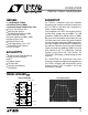
LT1203/LT1205
SYMBOL PARAMETER CONDITIONS MIN TYP MAX UNITS
SR Slew Rate (Note 6) 180 300 V/µs
FPBW Full Power Bandwidth (Note 7) V
OUT
= 2V
P-P
28.6 47.7 MHz
t
SEL
Channel-to-Channel Select Time (Note 8) R
L
= 10k 25 35 ns
Enable Time (Note 9) R
L
= 1k 25 35 ns
Disable Time (Note 9) R
L
= 1k 20 35 ns
t
r
, t
f
Small-Signal Rise and Fall Time V
OUT
= 250mV
P-P
, 10% to 90% 2.6 ns
Propagation Delay V
OUT
= 250mV
P-P
2.9 ns
Overshoot V
OUT
= 250mV
P-P
5%
Crosstalk (Note 10) R
S
= 10Ω 90 dB
Chip Disabled Crosstalk (Note 10) R
L
= 10Ω, EN Pin Voltage ≤ 0.8V 110 dB
Channel Select Output Transient All V
IN
= 0V 50 mV
P-P
t
S
Settling Time 1%, V
OUT
= 1V 30 ns
Differential Gain (Note 11) V
S
= ±15V, R
L
= 10k 0.02 %
Differential Phase (Note 11) V
S
= ±15V, R
L
= 10k 0.02 DEG
Insertion Loss R
L
= 100k, C
L
= 30pF, V
OUT
= 500mV
P-P
, f = 1MHz 0.02 dB
E
LECTR
IC
AL C CHARA TERIST
ICS
0°C ≤ T
A
≤ 70°C, ±5V ≤ V
S
≤ ±15V, R
L
= 1k, pulse tested, EN pin open or high, unless otherwise noted.
SYMBOL PARAMETER CONDITIONS MIN TYP MAX UNITS
V
OUT
Output Voltage V
S
= ±15V, V
IN
= ±2V, R
L
= 400Ω ● ±1.8 ±1.90 V
V
S
= ±5V, V
IN
= ±2V, R
L
= 1k ● ±1.8 ±1.94 V
Overload Swing (Note 1) V
S
= ±15V, V
IN
= ±5V ● ±0.9 ±1.5 V
V
S
= ±5V, V
IN
= ±5V ● ±0.9 ±1.5 V
I
OUT
Output Current V
S
= ±15V, V
IN
= ±2V, R
L
= 400Ω ● ±4.5 ±4.75 mA
V
S
= ±5V, V
IN
= ±2V, R
L
= 1k ● ±1.8 ±2.00 mA
R
OUT
Enabled Output Resistance EN Pin Voltage = 2V, V
OUT
= ±2V, V
S
= ±15V ● 20 42 Ω
Disabled Output Resistance EN Pin Voltage = 0.5V, V
OUT
= ±2V, V
S
= ±15V ● 110 MΩ
I
S
Supply Current (LT1203) EN Pin Voltage = 2V ● 10.0 14 mA
EN Pin Voltage = 0.5V
● 5.8 8 mA
Supply Current (LT1205) EN Pin Voltage = 2V ● 20.0 28 mA
EN Pin Voltage = 0.5V
● 11.6 16 mA
V
IL
Logic Low Logic Pin ● 0.8 V
V
IH
Logic High Logic Pin ● 2V
Enable Low EN Pin ● 0.5 V
Enable High EN Pin ● 2V
I
IL
Digital Input Current Low LT1203 Pin 5, LT1205 Pins 9, 13 = 0V ● 1.5 6.5 µA
I
IH
Digital Input Current High LT1203 Pin 5, LT1205 Pins 9, 13 = 5V ● 10 200 nA
I
EN
Enable Pin Current LT1203 Pin 6, LT1205 Pins 10, 14 ● 20 80 µA
CCHARA TERIST
ICS
AC
T
A
= 25°C, V
S
= ±15V, R
L
= 1k, EN pin open or high, unless otherwise noted.
The ● denotes specifications which apply over the specified
temperature range.
Note 1: The analog inputs (pins 1, 3 for the LT1203, pins 1, 3, 5, 7 for the
LT1205) are protected against ESD and overvoltage with internal SCRs.
For inputs ≤±2.8V the SCR will not fire. Voltages above 2.8V will fire the
SCR and the DC current should be limited to 20mA. To turn off the SCR
the pin voltage must be reduced to less than 1V or the current reduced to
less than 600µA.