
Datasheet


14
LT1251/LT1256
APPLICATIONS INFORMATION
WUU
U
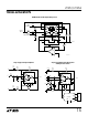
Control Circuit Description
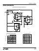
1251/56 F03
I
FS
I
C
I
C
V
C
V
FS
I
FS
R
FS
V
+
R
C
3
5
12
11
10
4
–
+
–
+
CONTROL V TO I FULL SCALE V TO I
CFS
R
FS
5k
R
C
5k
gain) is ±3% as detailed in the electrical tables. By using
a 2.5V full-scale voltage and the internal resistors, no
additional errors need be accounted for.
In the LT1256, K changes linearly with I
C
. To insure that K
is zero, V
C
must be negative 15mV or more to overcome
the worst-case control op amp offset. Similarly to insure
that K is 100%, V
C
must be 3% larger than V
FS
based on
the guaranteed gain accuracy.
To eliminate the overdrive requirement, the LT1251 has
internal circuitry that senses when the control current is at
about 5% and sets K to 0%. Similarly, at about 95% it sets
K to 100%. The LT1251 guarantees that a 2% (50mV)
input gives zero and 98% (2.45V) gives 100%.
The operating currents of the LT1251/LT1256 are derived
from I
FS
and therefore the quiescent current is a function
of V
FS
and R
FS
. The electrical tables show the supply
current for three values of V
FS
including zero. An approxi-
mate formula for the supply current is:
I
S
= 1mA + (24)(I
FS
) + (V
S
/20k)
where V
S
is the total supply voltage between Pins 9 and 7.
By reducing I
FS
the supply current can be reduced, how-
ever, the slew rate and bandwidth will also be reduced as
indicated in the characteristic curves. Using the internal
resistors (5k) with V
FS
equal to 2.5V results in I
FS
equal to
500µA; there is no reason to use a larger value of I
FS
.
The inverting inputs of the V-to-I converters are available
so that external resistors can be used instead of the
internal ones. For example, if a 10V full-scale voltage is
desired, an external pair of 20k resistors should be used to
set I
FS
to 500µA. The positive supply voltage must be 2.5V
greater than the maximum V
C
and/or V
FS
to keep the
transistors from saturating. Do not use the internal resis-
tors with external resistors because the internal resistors
have a large positive temperature coefficient (0.2%/°C)
that will cause gain errors.
If the control voltage is applied to the free end of resistor
R
C
(Pin 5) and the V
C
input (Pin 3) is grounded, the polarity
of the control voltage must be inverted. Therefore, K will
be 0% for zero input and 100% for –2.5V input, assuming
V
FS
equals 2.5V. With Pin 3 grounded, Pin 4 is a virtual
ground; this is convenient for summing several negative
going control signals.
The control section of the LT1251/LT1256 consists of two
identical voltage-to-current converters (V-to-I); each
V-to-I contains an op amp, an NPN transistor and a
resistor. The converter on the right generates a
full-scale
current I
FS
and the one on the left generates a
control
current I
C
. The ratio I
C
/I
FS
is called K. K goes from a
minimum of zero (when I
C
is zero) to a maximum of one
(when I
C
is equal to, or greater than, I
FS
). K determines the
gain from each signal input to the output.
The op amp in each V-to-I drives the transistor until the
voltage at the inverting input is the same as the voltage at
the noninverting input. If the open end of the resistor (Pin
5 or 10) is grounded, the voltage across the resistor is the
same as the voltage at the noninverting input. The emitter
current is therefore equal to the input voltage V
C
divided by
the resistor value R
C
. The collector current is essentially
the same as the emitter current and it is the ratio of the two
collector currents that sets the gain.
The LT1251/LT1256 are tested with Pins 5 and 10 grounded
and a full-scale voltage of 2.5V applied to V
FS
(Pin 12). This
sets I
FS
at approximately 500µA; the control voltage V
C
is
applied to Pin 3. When the control voltage is negative or
zero, I
C
is zero and K is zero. When V
C
is 2.5V or greater,
I
C
is equal to or greater than I
FS
and K is one. The gain of
channel one goes from 0% to 100% as V
C
goes from zero
to 2.5V. The gain of channel two goes the opposite way,
from 100% down to 0%. The worst-case error in K (the
Figure 3. Control Circuit Block Diagram