
Datasheet


LT1460
12
1460fc
TEMPERATURE (°C)
–50
OUTPUT VOLTAGE (V)
2.501
2.502
2.503
25 75
1460 G38
2.500
2.499
–25 0
50 100 125
2.498
2.497
THREE TYPICAL PARTS
INPUT VOLTAGE (V)
0
SUPPLY CURRENT (µA)
100
150
125°C
25°C
–55°C
20
1460 G39
50
0
5
10
15
250
200
INPUT VOLTAGE (V)
0
OUTPUT VOLTAGE (V)
2.502
2.501
2.500
2.499
2.498
2.497
2.496
2.495
2.494
16
1460 G40
4 8 12 20142 6 10 18
25°C
125°C
–55°C
INPUT-OUTPUT VOLTAGE (V)
0
0.1
OUTPUT CURRENT (mA)
10
125°C
25°C
100
0.5 1.0 1.5 2.0 2.5
1460 G35
1
–55°C
OUTPUT CURRENT (mA)
0.1
–2.0
OUTPUT VOLTAGE CHANGE (mV)
–1.0
0
1 10 100
1460 G36
–3.0
–2.5
–1.5
–0.5
–3.5
–4.0
–55°C
25°C
125°C
OUTPUT CURRENT (mA)
0
0
OUTPUT VOLTAGE CHANGE (mV)
20
40
60
80
100
120
1 2 3 4
–55°C
1460 G37
5
125°C
25°C
FREQUENCY (kHz)
20
POWER SUPPLY REJECTION RATIO (dB)
40
50
70
80
0.1 10 100 1000
1460 G41
0
1
60
30
10
FREQUENCY (kHz)
1
OUTPUT IMPEDANCE (Ω)
10
100
1000
0.01 1 10 100
0.1
0.1
1000
1460 G42
C
L
= 0µF
C
L
= 0.1µF
C
L
= 1µF
C
LOAD
= 0µF
200µs/DIV
LOAD CURRENT (mA)
10
20
1
0.1
1460 G43
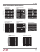
Characteristic curves are similar for all voltage
options of the LT1460S3. Curves from the LT1460S3-2.5 and the LT1460S3-10 represent the extremes of the voltage options.
Characteristic curves for other output voltages fall between these curves, and can be estimated based on their voltage output.
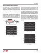
LT1460S3-2.5V Minimum Input-
Output Voltage Differential
LT1460S3-2.5V Load Regulation,
Sourcing
LT1460S3-2.5V Load Regulation,
Sinking
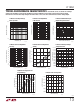
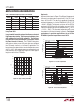
LT1460S3-2.5V Output Voltage
Temperature Drift
LT1460S3-2.5V Supply Current
vs Input Voltage
LT1460S3-2.5V Line Regulation
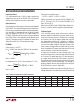
LT1460S3-2.5V Power Supply
Rejection Ratio vs Frequency
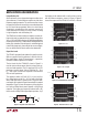
LT1460S3-2.5V Output Impedance
vs Frequency
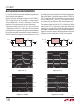
LT1460S3-2.5V Transient
Response
typical perForMance characteristics