
Datasheet


5
LT1461
2.5V Turn-On Time
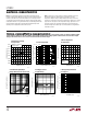
2.5V Output Impedance
vs Frequency 2.5V Turn-On Time
FREQUENCY (kHz)
0.01
1
OUTPUT IMPEDANCE (Ω)
10
100
1000
0.1 1 10
1461 G07
C
OUT
= 2µF
C
OUT
= 1µF
TIME (100µs/DIV)
VOLTAGE (V)
V
IN
20
10
0
2
1
0
1461 G08
C
IN
= 1µF
C
L
= 2µF
R
L
=
∞
V
OUT
TIME (100µs/DIV)
VOLTAGE (V)
V
IN
20
10
0
2
1
0
1461 G09
C
IN
= 1µF
C
L
= 2µF
R
L
= 50Ω
V
OUT
TYPICAL PERFOR A CE CHARACTERISTICS
UW
Characteristic curves are similar for most LT1461s.
Curves from the LT1461-2.5 and the LT1461-5 represent the extremes of the voltage options. Characteristic curves for other output
voltages fall between these curves and can be estimated based on their output.
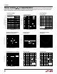
2.5V Transient Response to 10mA
Load Step
I
OUT
0mA
10mA/DIV
V
OUT
50mV/DIV
1461 G10
2.5V Line Transient Response
5V
V
IN
V
OUT
50mV/DIV
1461 G11
C
IN
= 0.1µF
2.5V Output Noise
0.1Hz ≤ f ≤ 10Hz
C
L
= 2µF
TIME (2SEC/DIV)
OUTPUT NOISE (10µV/DIV)
1461 G12
4V