
Datasheet


LT1498/LT1499
14989fg
17
APPLICATIONS INFORMATION
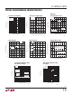
Figure 1. LT1498 Simplifi ed Schematic Diagram
Rail-to-Rail Input and Output
The LT1498/LT1499 are fully functional for an input and
output signal range from the negative supply to the posi-
tive supply. Figure 1 shows a simplifi ed schematic of the
amplifi er. The input stage consists of two differential am-
plifi ers, a PNP stage (Q1/Q2) and an NPN stage (Q3/Q4)
which are active over different ranges of input common
mode voltage. A complementary common emitter output
stage (Q14/Q15) is employed allowing the output to swing
from rail-to-rail. The devices are fabricated on Linear
Technology’s proprietary complementary bipolar process
to ensure very similar DC and AC characteristics for the
output devices (Q14/Q15).
The PNP differential input pair is active for input com-
mon mode voltages, V
CM
, between the negative supply
to approximately 1.3V below the positive supply. As V
CM
moves further toward the positive supply, the transistor
(Q5) will steer the tail current, I
1
, to the current mirror
(Q6/Q7) activating the NPN differential pair, and the PNP
differential pair becomes inactive for the rest of the input
common mode range up to the positive supply.
The output is confi gured with a pair of complementary
common emitter stages that enables the output to swing
from rail to rail. Capacitors (C1 and C2) form local
feedback loops that lower the output impedance at high
frequencies.
Input Offset Voltage
The offset voltage changes depending upon which input
stage is active. The input offsets are random, but are
trimmed to less than 475μV. To maintain the precision
characteristics of the amplifi er, the change of V
OS
over the
entire input common mode range (CMRR) is guaranteed
to be less than 425μV on a single 5V supply.
Input Bias Current
The input bias current polarity also depends on the input
common mode voltage, as described in the previous sec-
tion. When the PNP differential pair is active, the input bias
currents fl ow out of the input pins; they fl ow in opposite
direction when the NPN input stage is active. The offset error
due to input bias current can be minimized by equalizing
the noninverting and inverting input source impedances.
This will reduce the error since the input offset currents
are much less than the input bias currents.
Q4
Q6
V
BIAS
D6D5
+IN
D2
Q3
Q7
Q1
I
1
Q9
Q2
D4
D1
D3
–IN
OUT
V
–
V
+
Q5
Q12
Q10
Q8
Q14
14989 F01
C1
R1
R6
R3
V
–
C
C
R4 R5
C2
R2
Q11 Q13
Q15
BUFFER
AND
OUTPUT BIAS
R7