
Datasheet


12
LT1513/LT1513-2
sn1513 1513fas
APPLICATIONS INFORMATION
WUU
U
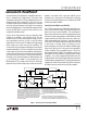
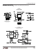
The suggested way to control unity loop frequency is to
increase the filter time constant on the I
FB
pin (R4/C4 in
Figures 1 and 7). The filter resistor cannot be arbitrarily
increased because high values will affect charging current
accuracy. Charging current will increase by 1% for each
40Ω increase in R4. There is no inherent limitation on the
value of C4, but if this capacitor is ceramic, it should be an
X7R type to maintain its value over temperature. X7R
dielectric requires a larger footprint.
The formula for calculating the minimum value for the filter
capacitor C4 is:
C
RV R
fR V V
IN
IN BAT
4
3 4 12 1500 5
24
=
+
()()( )()( )()
()( )( )
µ
π
V
IN
= Highest input voltage
1500µ = Transconductance of error amplifier
(EA)f = Desired unity-gain frequency
V
BAT
= Battery voltage
For example, assume V
IN(MAX)
= 15V, R3 = 0.4Ω (charging
current set to 0.25A), R4 = 24Ω, R5 = 330Ω and V
BAT
= 8V,
CF4
0 4 4 15 12 0 0015 330
15 8
1=
+
=
. ( )( )( )( . )( )
)6.3(25000)(39)(
µ
The value for C4 could be reduced to a more manageable size
by increasing R4 to 75Ω and reducing R5 to 300Ω, yielding
0.47µF for C4. The 2% increase in charging current can be
ignored or factored into the value for R3.
More Help
Linear Technology Field Application Engineers have a CAD
spreadsheet program for detailed calculations of circuit
operating conditions. In addition, our Applications Depart-
ment is always ready to lend a helping hand. The LT1371
data sheet may also be helpful. The LT1513 is identical
except for the current amplifier circuitry.