
Datasheet


10
LT1528
1528fa
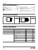
The reverse output current will follow the curve in Figure
3 when the input is pulled to ground. This current flows
through the OUTPUT pin to ground. The state of the
SHDN pin will have no effect on output current when the
input pin is pulled to ground.
In some applications it may be necessary to leave the input
on the LT1528 unconnected when the output is held high.
This can happen when the LT1528 is powered from a
rectified AC source. If the AC source is removed, then the
input of the LT1528 is effectively left floating. The reverse
output current also follows the curve in Figure 3 if the input
pin is left open. The state of the SHDN pin will have no
effect on the reverse output current when the input pin is
floating.
When the input of the LT1528 is forced to a voltage below
its nominal output voltage and its output is held high, the
output current will follow the curve shown in Figure 3. This
can happen if the input of the LT1528 is connected to a low
voltage and the output is held up by a second regulator
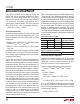
circuit. When the input pin is forced below the 0utput pin
or the OUTPUT pin is pulled above the input pin, the input
current will typically drop to less than 2µA (see Figure 4).
The state of the SHDN pin will have no effect on the reverse
output current when the output is pulled above the input.
Figure 3. Reverse Output Current
OUTPUT VOLTAGE (V)
0
OUTPUT CURRENT (µA)
1000
900
800
700
600
500
400
300
200
100
0
8
LT1528 • F03
213579
4
6
10
T
J
= 25°C, V
IN
= 0V
V
OUT
= V
SENSE
CURRENT FLOWS
INTO DEVICE
Figure 4. Input Current
INPUT VOLTAGE (V)
0
0
INPUT CURRENT (µA)
2
5
1.0
2.0
2.5
LT1528 • F04
1
4
3
0.5
1.5
3.0
3.5
V
OUT
= 3.3V
APPLICATIO S I FOR ATIO
WUUU