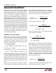
LT1576/LT1576-5 1.5A, 200kHz Step-Down Switching Regulator U FEATURES ■ ■ ■ ■ ■ ■ ■ ■ ■ ■ ■ DESCRIPTIO The LT ®1576 is a 200kHz monolithic buck mode switching regulator. A 1.5A switch is included on the die along with all the necessary oscillator, control and logic circuitry. The topology is current mode for fast transient response and good loop stability. The LT1576 is a modified version of the industry standard LT1376 optimized for noise sensitive applications. Constant 200kHz Switching Frequency 1.
LT1576/LT1576-5 W U U U W W W ABSOLUTE MAXIMUM RATINGS PACKAGE/ORDER INFORMATION (Note 1) Input Voltage .......................................................... 25V BOOST Pin Above Input Voltage ............................. 10V SHDN Pin Voltage .................................................. 6.5V BIAS Pin Voltage ...................................................... 7V FB Pin Voltage (Adjustable Part) ............................ 3.5V FB Pin Current (Adjustable Part) ........................
LT1576/LT1576-5 ELECTRICAL CHARACTERISTICS The ● denotes specifications which apply over the full operating temperature range, otherwise specifications are TA, TJ = 25°C, VIN = 15V, VC = 1.5V, Boost = VIN + 5V, switch open, unless otherwise noted.
LT1576/LT1576-5 U W TYPICAL PERFORMANCE CHARACTERISTICS Switch Drop Switch Peak Current Limit 0.5 TYPICAL 25°C 0.3 –20°C 0.2 0.1 2.0 FEEDBACK VOLTAGE (V) SWITCH PEAK CURRENT (A) 125°C 0.4 MINIMUM 1.5 1.0 0.5 0 0 0 0.25 0.50 0.75 1.00 SWITCH CURRENT (A) 1.25 20 0 1.50 60 40 DUTY CYCLE (%) 80 1.21 1.20 1576 G02 1576 G01 Shutdown Pin Bias Current AT 2.44V STANDBY THRESHOLD (CURRENT FLOWS OUT OF PIN) Shutdown Thresholds 180 0.8 160 0.
LT1576/LT1576-5 U W TYPICAL PERFORMANCE CHARACTERISTICS Shutdown Supply Current Error Amplifier Transconductance 100 Frequency Foldback 1600 250 75 VIN = 25V VIN = 10V 50 25 SWITCHING FREQUENCY SWITCHING FREQUENCY (kHz) OR CURRENT (µA) TRANSCONDUCTANCE (µMho) INPUT SUPPLY CURRENT (µA) 1400 1200 1000 800 600 400 200 150 100 50 200 0 0.2 0.3 0.1 SHUTDOWN VOLTAGE (V) 0 1576 G10 0 125 1.0 0.5 1.5 FEEDBACK VOLTAGE (V) 0 2.
LT1576/LT1576-5 U W TYPICAL PERFORMANCE CHARACTERISTICS BOOST Pin Current VC Pin Shutdown Threshold 30 1.0 THRESHOLD VOLTAGE (V) BOOST PIN CURRENT (mA) 25 20 15 10 5 0 0 0.25 0.50 0.75 1.00 SWITCH CURRENT (A) 1.25 1.50 1576 G19 0.8 0.6 0.4 0.2 0 0 25 50 75 100 –50 –25 JUNCTION TEMPERATURE (°C) 125 1576 G20 U U U PIN FUNCTIONS VSW (Pin 1): The switch pin is the emitter of the on-chip power NPN switch. This pin is driven up to the input pin voltage during switch on time.
LT1576/LT1576-5 U U U PIN FUNCTIONS This pin sits at about 1V for very light loads and 2V at maximum load. It can be driven to ground to shut off the regulator, but if driven high, current must be limited to 4mA. FB/SENSE (Pin 7): The feedback pin is the input to the error amplifier which is referenced to an internal 1.21V source. An external resistive divider is used to set the output voltage. Three additional functions are performed by the FB pin.
LT1576/LT1576-5 W BLOCK DIAGRAM 0.025Ω INPUT + BIAS 2.9V BIAS REGULATOR – CURRENT SENSE AMPLIFIER VOLTAGE GAIN = 35 INTERNAL VCC SLOPE COMP Σ BOOST 0.8V 200kHz OSCILLATOR SYNC S CURRENT COMPARATOR + SHUTDOWN COMPARATOR RS FLIP-FLOP DRIVER CIRCUITRY R – Q1 POWER SWITCH VSW – + 0.4V FREQUENCY SHIFT CIRCUIT SHDN 3.5µA FOLDBACK CURRENT LIMIT CLAMP + Q2 – LOCKOUT COMPARATOR ERROR AMPLIFIER gm = 1000µMho VC 2.44V FB + – 1.21V GND 1576 BD Figure 1.
LT1576/LT1576-5 U U W U APPLICATIONS INFORMATION sufficiently low duty cycle if switching frequency were maintained at 200kHz, so frequency is reduced by about 5:1 when the feedback pin voltage drops below 0.7V (see Frequency Foldback graph). This does not affect operation with normal load conditions; one simply sees a gear shift in switching frequency during start-up as the output voltage rises.
LT1576/LT1576-5 U W U U APPLICATIONS INFORMATION The internal circuitry which forces reduced switching frequency also causes current to flow out of the feedback pin when output voltage is low. The equivalent circuitry is shown in Figure 2. Q1 is completely off during normal operation. If the FB pin falls below 0.7V, Q1 begins to conduct current and reduces frequency at the rate of approximately 1kHz/µA.
LT1576/LT1576-5 U U W U APPLICATIONS INFORMATION IOUT(MAX) = Discontinuous mode (IP) (f)(L)(VIN) 2(VOUT )(VIN − VOUT ) 2 Example: with L = 5µH, VOUT = 5V, and VIN(MAX) = 15V, (1.5) 200 • 103 5 •10−6 (15) IOUT(MAX ) = = 0.34A 2(5)(15 − 5) 2 The main reason for using such a tiny inductor is that it is physically very small, but keep in mind that peak-to-peak inductor current will be very high. This will increase output ripple voltage.
LT1576/LT1576-5 U U W U APPLICATIONS INFORMATION 5. After making an initial choice, consider the secondary things like output voltage ripple, second sourcing, etc. Use the experts in the Linear Technology’s applications department if you feel uncertain about the final choice. They have experience with a wide range of inductor types and can tell you about the latest developments in low profile, surface mounting, etc. Table 2 VENDOR/ PART NO.
LT1576/LT1576-5 U U W U APPLICATIONS INFORMATION Output Capacitor Ripple Current (RMS): IRIPPLE(RMS) = ( )( (L)(f)(V ) 0.29 VOUT VIN − VOUT ) IN Ceramic Capacitors Higher value, lower cost ceramic capacitors are now becoming available in smaller case sizes. These are tempting for switching regulator use because of their very low ESR. Unfortunately, the ESR is so low that it can cause loop stability problems.
LT1576/LT1576-5 U W U U APPLICATIONS INFORMATION This formula will not yield values higher than 1A with maximum load current of 1.25A unless the ratio of input to output voltage exceeds 5:1. The only reason to consider a larger diode is the worst-case condition of a high input voltage and overloaded (not shorted) output.
LT1576/LT1576-5 U U W U APPLICATIONS INFORMATION RFB LT1576 OUTPUT VSW IN INPUT 2.44V – STANDBY RHI + 3.5µA + SHDN + TOTAL SHUTDOWN RLO C1 0.4V – GND 1576 F04 Figure 4. Undervoltage Lockout Threshold voltage for lockout is about 2.44V. A 3.5µA bias current flows out of the pin at threshold. This internally generated current is used to force a default high state on the shutdown pin if the pin is left open.
LT1576/LT1576-5 U U W U APPLICATIONS INFORMATION SWITCH NODE CONSIDERATIONS For maximum efficiency, switch rise and fall times are made as short as possible. To prevent radiation and high frequency resonance problems, proper layout of the components connected to the switch node is essential. B field (magnetic) radiation is minimized by keeping catch diode, switch pin, and input bypass capacitor leads as short as possible.
LT1576/LT1576-5 U W U U APPLICATIONS INFORMATION including the switch, catch diode, and input capacitor is the only one containing nanosecond rise and fall times. If you follow this path on the PC layout, you will see that it is irreducibly short. If you move the diode or input capacitor away from the LT1576, get your resumé in order. The other paths contain only some combination of DC and 200kHz triwave, so are much less critical.
LT1576/LT1576-5 U U W U APPLICATIONS INFORMATION guarantee power sharing. The actual value of the capacitor in microfarads is not particularly important because at 200kHz, any value above 15µF is essentially resistive. RMS ripple current rating is the critical parameter. Actual RMS current can be calculated from: ( ) IRIPPLE RMS = IOUT VOUT VIN − VOUT / VIN ( ) 2 The term inside the radical has a maximum value of 0.5 when input voltage is twice output, and stays near 0.
LT1576/LT1576-5 U U W U APPLICATIONS INFORMATION At power-up, when VC is being clamped by the FB pin (see Figure 2, Q2), the sync function is disabled. This allows the frequency foldback to operate in the shorted output condition. During normal operation, switching frequency is controlled by the internal oscillator until the FB pin reaches 0.7V, after which the SYNC pin becomes operational. If no synchronization is required, this pin should be connected to ground.
LT1576/LT1576-5 U U W U APPLICATIONS INFORMATION the output. Gain is set by the 1.5A/V transconductance of the LT1576 power section and the effective complex impedance from output to ground. Gain rolls off smoothly above the 160Hz pole frequency set by the 100µF output capacitor. Phase drop is limited to about 85°. Phase recovers and gain levels off at the zero frequency (≈16kHz) set by capacitor ESR (0.1Ω). Error amplifier transconductance phase and gain are shown in Figure 11.
LT1576/LT1576-5 U W U U APPLICATIONS INFORMATION Analog experts will note that around 7kHz, phase dips close to the zero phase margin line. This is typical of switching regulators, especially those that operate over a wide range of loads. This region of low phase is not a problem as long as it does not occur near unity-gain. In practice, the variability of output capacitor ESR tends to dominate all other effects with respect to loop response.
LT1576/LT1576-5 U W U U APPLICATIONS INFORMATION How Do I Test Loop Stability? The “standard” compensation for LT1576 is a 100pF capacitor for CC, with RC = 0Ω. While this compensation will work for most applications, the “optimum” value for loop compensation components depends, to various extent, on parameters which are not well controlled.
LT1576/LT1576-5 U W U U APPLICATIONS INFORMATION The output of the regulator contains both the desired low frequency transient information and a reasonable amount of high frequency (200kHz) ripple. The ripple makes it difficult to observe the small transient, so a two-pole, 100kHz filter has been added. This filter is not particularly critical; even if it attenuated the transient signal slightly, this wouldn’t matter because amplitude is not critical.
LT1576/LT1576-5 U U W U APPLICATIONS INFORMATION Maximum load current: ( )( ) ( )( )( ) )( VIN VOUT VOUT VIN − 0.35 IP − 2 VOUT + VIN f L IMAX = VOUT + VIN − 0.35 VOUT + VF ( ( )( ) ) IP = Maximum rated switch current VIN = Minimum input voltage VOUT = Output voltage VF = Catch diode forward voltage 0.35 = Switch voltage drop at 1.5A Example: with VIN(MIN) = 5.5V, VOUT = 5V, L = 30µH, VF = 0.5V, IP = 1.5A: IMAX = 0.6A.
LT1576/LT1576-5 U U W U APPLICATIONS INFORMATION inductor is therefore typically based on ensuring that peak switch current rating is not exceeded. This gives the lowest value of inductance that can be used, but in some cases (lower output load currents) it may give a value that creates unnecessarily high output ripple voltage. A compromise value is often chosen that reduces output ripple.
LT1576/LT1576-5 U W U U APPLICATIONS INFORMATION Ripple Current in the Input and Output Capacitors Diode Current Positive-to-negative converters have high ripple current in both the input and output capacitors. For long capacitor lifetime, the RMS value of this current must be less than the high frequency ripple current rating of the capacitor. The following formula will give an approximate value for RMS ripple current. This formula assumes continuous mode and large inductor value.
LT1576/LT1576-5 U PACKAGE DESCRIPTION Dimensions in inches (millimeters) unless otherwise noted. S8 Package 8-Lead Plastic Small Outline (Narrow 0.150) (LTC DWG # 05-08-1610) 0.189 – 0.197* (4.801 – 5.004) 8 7 6 5 0.150 – 0.157** (3.810 – 3.988) 0.228 – 0.244 (5.791 – 6.197) 1 0.010 – 0.020 × 45° (0.254 – 0.508) 0.008 – 0.010 (0.203 – 0.254) 0.053 – 0.069 (1.346 – 1.752) 0°– 8° TYP 0.016 – 0.050 (0.406 – 1.270) 0.014 – 0.019 (0.355 – 0.483) TYP *DIMENSION DOES NOT INCLUDE MOLD FLASH.
LT1576/LT1576-5 U TYPICAL APPLICATION Dual Output SEPIC␣ Converter losses. C4 provides a low impedance path to maintain an equal voltage swing in L1B, improving regulation. In a flyback converter, during switch on time, all the converter’s energy is stored in L1A only, since no current flows in L1B. At switch off, energy is transferred by magnetic coupling into L1B, powering the – 5V rail. C4 pulls L1B positive during switch on time, causing current to flow, and energy to build in L1B and C4.