
Datasheet


9
LT1616
C
OUT
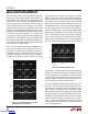
= 4.7µF CERAMIC, CASE SIZE 0805
C
OUT
= 10µF CERAMIC, CASE SIZE 1206
C
OUT
= 47µF, ESR ≅ 0.080Ω (SANYO POSCAP 6TPA47M)
C CASE
C
OUT
= 100µF, ESR ≅ 0.150Ω (TANTALUM AVX
TPSC107M006R0150) C CASE
C
OUT
= 100µF TANTALUM AND 2.2µF CERAMIC
Figure 3. Transient Load Response of the LT1616
APPLICATIO S I FOR ATIO
WUUU
V
IN
BOOST
GND FB
SHDN SW
5
V
IN
10V
4
1
6
10µH
23
LT1616
1616 F04
V
OUT
3.3V
C
OUT
33Ω
22Ω
Figure 4. Circuit Used for Transient Load Test Shown in Figure 3
V
OUT
20mV/DIV
I
LOAD
100mA/DIV
0
Regardless of which capacitor or combination of capaci-
tors you choose, you should do transient load tests to
evaluate the circuit’s stability. Avoid capacitors or combi-
nations that result in a ringing response. Problems may
occur if the output capacitance is very low or if a high value
inductor is used in combination with a large value, low
ESR capacitor.
The high performance (low ESR), small size and robust-
ness of ceramic capacitors make them the preferred type
for LT1616 applications. However, all ceramic capacitors
are not the same. Many of the higher value capacitors use
poor dielectrics with high temperature and voltage
coefficients. In particular, Y5V types should be regarded
with suspicion. Stick with X7R and X5R types. Don’t be
afraid to run them at their rated voltage. Table 2 lists
several capacitor manufacturers.
Catch Diode
A 0.5A Schottky diode is recommended for the catch diode
D1. The ON Semiconductor MBR0530 is a good choice; it
is rated for 0.5A forward current and a maximum reverse
voltage of 30V. For circuits with V
IN
less than 20V, the
MBR0520L can be used. Other suitable diodes are the
Zetex ZHCS500TR and ZHCS750TR, and various versions
of the 1N5818.
Downloaded from Arrow.com.Downloaded from Arrow.com.Downloaded from Arrow.com.Downloaded from Arrow.com.Downloaded from Arrow.com.Downloaded from Arrow.com.Downloaded from Arrow.com.Downloaded from Arrow.com.Downloaded from Arrow.com.