
Datasheet


1
LT1620/LT1621
Rail-to-Rail Current
Sense Amplifier
S
F
EA
T
U
RE
■
Accurate Output Current Programming
■
Usable in Charging Applications Up to 32V Output
■
Programmable Load Current Monitor for End-of-
Charging-Cycle Notification (16-Pin Version)
■
Dual Function IC (LT1621) Allows Convenient
Integration of Load and Input Current Sensing
■
Level-Shifted Current Sense Output for Current Mode
PWM Controllers
■
Can be Used for NiCd, NiMH, Lead-Acid and Lithium-
Ion Battery Charging
■
Greater than 96% Efficiency Possible in Charger
Applications
■
High Output Currents Possible: > 10A
Easily Obtained
D
U
ESCRIPTIO
The LT
®
1620 simplifies the design of high performance,
controlled current battery charging circuits when used in
conjunction with a current mode PWM controller IC.
The LT1620 regulates average output current independent
of input and output voltage variations. Output current can
be easily adjusted via a programming voltage applied to
the LT1620’s PROG pin.
Most current mode PWM controllers have limited output
voltage range because of common mode limitations on the
current sense inputs. The LT1620 overcomes this restric-
tion by providing a level-shifted current sense signal,
allowing a 0V to 32V output voltage range.
The 16-pin version of the LT1620 contains a program-
mable low charging current flag output. This output flag
can be used to signal when a Li-Ion battery charging cycle
is nearing completion.
The LT1621 incorporates two fully independent current
control circuits for dual loop applications.
U
A
O
PP
L
IC
AT
ITY
P
I
CA
L
, LTC and LT are registered trademarks of Linear Technology Corporation.
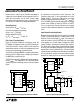
BATTERY CHARGE CURRENT (A)
0
EFFICIENCY (%)
90
95
100
4
1620/21 • TA02
85
80
75
1
2
3
5
V
IN
= 24V
V
BATT
= 16V
V
BATT
= 12V
V
BATT
= 6V
Efficiency
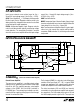
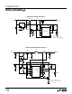
Figure 1. Low Dropout, High Current Li-Ion Battery Charger
FB
I
TH
LTC1435
SYNCHRONOUS
BUCK
REGULATOR
AVG
SENSE
LT1620MS8
V
CC
GND
18
6
3
V
BATT
I
BATT
TO 4A
V
IN
(V
BATT
+ 0.5V) TO 32V
LT1620/21 • F01
IN
–
IN
+
I
OUT
PROG
45
27
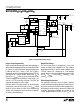
SIMPLIFIED SCHEMATIC. SEE FIGURE 2 FOR COMPLETE SCHEMATIC
0.1µF
15.75k
1%
3k
1%
0.1µF
SENSE
–
INTV
CC
V
IN
SW
27µH
0.025Ω
22µF
35V
× 2
1.43M
0.1%
110k
0.1%
22µF
35V
+
+
U
S
A
O
PP
L
IC
AT
I
■
High Current Battery Chargers
■
High Output Voltage DC/DC Converters
■
Constant Current Sources
■
Overcurrent Fault Protectors