
Datasheet


5
LT1620/LT1621
OPERATION
U
used as integration nodes to facilitate averaging of the
current sense amplifier signal. (Note: filter capacitors on
these pins should bypass to the V
CC
supply.) Integration
of these signals enables direct sensing and control of DC
load current, eliminating the inclusion of ripple current in
load determination.
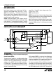
Transconductance Amplifier
The transconductance amplifier converts the difference
between the current programming input voltage (V
PROG
)
and the average current sense output (V
AVG
) into a current
at the amplifier output pin (I
OUT
). The amplifier output is
unidirectional and only sinks current. The amplifier is
designed to operate at a typical output current of 130µA
(Refer to the Functional Block Diagram)
with V
AVG
= V
PROG
. In typical PWM/charger type applica-
tions, the I
OUT
current is used to servo the current control
loop on the mated PWM controller IC to maintain a
programmed load current.
Comparator
The comparator circuit (available only in the LT1620GN)
may be used as an end-of-cycle sensor in a Li-Ion battery
charging system. The comparator detects when the charg-
ing current has fallen to a small value (typically 20% of the
maximum charging current). The comparator drives an open
collector output (MODE) that pulls low when the V
AVG2
voltage is more positive than V
PROG2
(output current below
the programmed threshold).
APPLICATIONS INFORMATION
WUU
U
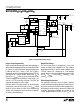
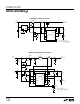
In Figure 2, an LT1620MS8 is coupled with an LTC1435
switching regulator in a high performance lithium-ion
battery charger application. The LTC1435 switching regu-
lator delivers extremely low dropout as it is capable of
approximately 99% duty cycle operation. No additional
power supply voltage is required for the LT1620 in this
application; it is powered directly from a 5V local supply
generated by the LTC1435. The DC charge current control
and high common mode current sense range of the
LT1620 combine with the low dropout capabilities of the
LTC1435 to make a 4-cell Li-Ion battery charger with over
96% efficiency, and only 0.5V input-to-output drop at 3A
charging current. Refer to the LTC1435 data sheet (available
from the LTC factory) for additional information on IC func-
tionality, performance and associated component selection.
This LT1620/LTC1435 battery charger is designed to yield
a 16.8V float voltage with a battery charge current of 3.2A.
The V
IN
supply can range from 17.3V to 28V (limited by the
switch MOSFETs). The charger provides a constant 3.2A
charge current until the battery voltage reaches the pro-
grammed float voltage. Once the float voltage is achieved,
a precision voltage regulation loop takes control, allowing
the charge current to fall as required to complete the
battery charge cycle.
R
SENSE
Selection
The LT1620 will operate throughout a current program-
ming voltage (V
PROG
) range of 0V to –1.25V (relative to
V
CC
), however, optimum accuracy will be obtained with a
current setting program voltage of –0.8V, corresponding
to 80mV differential voltage across the current sense
amplifier inputs. Given the desired current requirement,
selection of the load current sense resistor R
SENSE
is
possible. For the desired 3.2A charge current;
R
SENSE
= 80mV/3.2A or 0.025Ω
At the programmed 3.2A charge current, the sense resis-
tor will dissipate (0.08V)(3.20A) = 0.256W, and must be
rated accordingly.
Current Sense
The current sense inputs are connected on either side of
the sense resistor with IN
+
at the more positive potential,
given average charging current flow. The sense resistor to
IN
+
, IN
–
input paths should be connected using twisted
pair or minimum PC trace spacing for noise immunity.
Keep lead lengths short and away from noise sources for
best performance.