
Datasheet


7
LT1620/LT1621
APPLICATIONS INFORMATION
WUU
U
between the IN
+
and IN
–
inputs. Effective decoupling of
supply rails is also imperative in these types of circuits, as
large current transients are the norm. Power supply
decoupling should be placed as close as possible to the
ICs, and each IC should have a dedicated capacitor.
Design Equations
Sense resistor: R
SENSE
= V
ID
/I
MAX
Current limit programming voltage:
V
PROG
= V
CC
–[(10)(V
ID
)]
Voltage feedback resistors:
R
F1
/R
F2
= (V
BATT(FLOAT)
– 1.19)/1.19
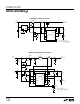
End-of-Cycle Flag Application
Figure 3 illustrates additional connections using the
LT1620GN, including the end-of-cycle (EOC) flag feature.
The EOC threshold is used to notify the user when the
required load current has fallen to a programmed value,
usually a given percentage of maximum load.
The end-of-cycle output (MODE) is an open-collector pull-
down; the circuit in Figure 3 uses a 10k pull-up resistor on
the MODE pin, connected to V
CC
.
The EOC flag threshold is determined through program-
ming V
PROG2
. The magnitude of this threshold corre-
sponds to 20 times the voltage across the sense amplifier
inputs.
As mentioned in the previous circuit discussion, the
charging current level is set to correspond to a sense
voltage of 80mV. The circuit in Figure 3 uses a resistor
divider to create a programming voltage (V
CC
–V
PROG2
)of
0.5V. The MODE flag will therefore trip when the charging
current sense voltage has fallen to 0.5V/20 or 0.025V.
Thus, the end-of-cycle flag will trip when the charging
current has been reduced to about 30% of the maximum
value.
Input Current Sensing Application
Monitoring the load placed on the V
IN
supply of a charging
system is achieved by placing a second current sense
resistor in front of the charger V
IN
input. This function is
useful for systems that will overstress the input supply
(wall adapter, etc.) if both battery charging and other
system functions simultaneously require high currents.
This allows use of input supply systems that are capable
of driving full-load battery charging and full-load system
requirements, but not simultaneously. If the input supply
current exceeds a predetermined value due to a combina-
tion of high battery charge current and external system
demand, the input current sense function automatically
Figure 3. End-of-Cycle Flag Implementation with LT1620GN
Figure 4. Input Current Sensing Application
AVG
PROG
PROG2
AVG2
V
CC
IN
+
SENSE
I
OUT
V
EE
MODE
IN
–
LT1620GN
LT1620/21 • F03
CONNECTED AS IN FIGURE 2
R1
5.5k
R2
50k
C2
3.3µF
C1, 3.3µF
R3
10k
END-OF-CYCLE
(ACTIVE LOW)
+
+
AVG
PROG
V
CC
IN
+
SENSE
LT1620MS8
1
2
3
4
8
7
I
OUT
GND
IN
–
6
5
V
SW
7
V
IN
5
81
V
FB
6
S/S
2
I
FB
4
GND
GND
TAB
3
C1
1µF
22µF
R
P1
3k
1%
R
P2
12k
1%
C2
1µF
R1
0.033Ω
L1B
10µH
22µF
TO
SYSTEM LOAD
4.7µF
L1A
10µH
24Ω
V
C
0.22µF
0.1µF
X7R
LT1513
RUN
5V
57k
6.4k
22µF
× 2
MBRS340
V
BATT
= 12.3V
1620/21 • F04
R
SENSE
0.1Ω
+
+
+
Li-ION