
Datasheet


LT1720/LT1721
10
17201fc
The exact amount of hysteresis will vary from part to part
as indicated in the specifi cations table. The hysteresis level
will also vary slightly with changes in supply voltage and
common mode voltage. A key advantage of the LT1720/
LT1721 is the signifi cant reduction in these effects, which
is important whenever an LT1720/LT1721 is used to detect
a threshold crossing in one direction only. In such a case,
the relevant trip point will be all that matters, and a stable
offset voltage with an unpredictable level of hysteresis,
as seen in competing comparators, is of little value. The
LT1720/LT1721 are many times better than prior compara-
tors in these regards. In fact, the CMRR and PSRR tests are
performed by checking for changes in either trip point to
the limits indicated in the specifi cations table. Because the
offset voltage is the average of the trip points, the CMRR
and PSRR of the offset voltage is therefore guaranteed to
be at least as good as those limits. This more stringent
test also puts a limit on the common mode and power
supply dependence of the hysteresis voltage.
Additional hysteresis may be added externally. The
rail-to-rail outputs of the LT1720/LT1721 make this more
predictable than with TTL output comparators due to the
LT1720/LT1721’s small variability of V
OH
(output high
voltage).
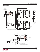
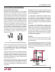
To add additional hysteresis, set up positive feedback
by adding additional external resistor R3 as shown in
Figure 3. Resistor R3 adds a portion of the output to the
threshold set by the resistor string. The LT1720/LT1721
pulls the outputs to the supply rail and ground to within
200mV of the rails with light loads, and to within 400mV
with heavy loads. For the load of most circuits, a good
APPLICATIONS INFORMATION
model for the voltage on the right side of R3 is 300mV or
V
CC
– 300mV, for a total voltage swing of (V
CC
– 300mV)
– 300mV = V
CC
– 600mV.
With this in mind, calculation of the resistor values needed
is a two-step process. First, calculate the value of R3 based
on the additional hysteresis desired, the output voltage
swing, and the impedance of the primary bias string:
R3 = (R1 || R2)(V
CC
– 0.6V)/(additional hysteresis)
Additional hysteresis is the desired overall hysteresis less
the internal 3.5mV hysteresis.
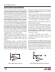
The second step is to recalculate R2 to set the same av-
erage threshold as before. The average threshold before
was set at V
TH
= (V
REF
)(R1)/(R1 + R2). The new R2 is
calculated based on the average output voltage (V
CC
/2)
and the simplifi ed circuit model in Figure 4. To assure
that the comparator’s noninverting input is, on average,
the same V
TH
as before:
R2′ = (V
REF
– V
TH
)/(V
TH
/R1 + (V
TH
– V
CC
/2)/R3)
For additional hysteresis of 10mV or less, it is not
uncommon for R2′ to be the same as R2 within 1%
resistor tolerances.
This method will work for additional hysteresis of up to
a few hundred millivolts. Beyond that, the impedance of
R3 is low enough to effect the bias string, and adjust-
ment of R1 may also be required. Note that the currents
through the R1/R2 bias string should be many times the
input currents of the LT1720/LT1721. For 5% accuracy,
the current must be at least 120μA(6μA I
B
÷ 0.05); more
for higher accuracy.
Figure 3. Additional External Hysteresis
–
+
1/2 LT1720
INPUT
17201 F03
R2
V
REF
R3
R1
Figure 4. Model for Additional Hysteresis Calculations
–
+
1/2 LT1720
17201 F04
R2a
V
REF
V
TH
R3
V
CC
2
V
AVERAGE
=
R1