
Datasheet

LT1766/LT1766-5
13
1766fc
APPLICATIONS INFORMATION
the high side for discontinuous mode, so it can be used
for all conditions.
II
I
I
VVV
VfL
PEAK OUT
LP P
OUT
OUT IN OUT
IN
=+ =+
()( )
()( )()()
()
–
-
2
2
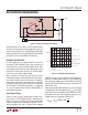
EMI
Decide if the design can tolerate an open core geometry like
a rod or barrel, which have high magnetic fi eld radiation,
or whether it needs a closed core like a toroid to prevent
EMI problems. This is a tough decision because the rods
or barrels are temptingly cheap and small and there are
no helpful guidelines to calculate when the magnetic fi eld
radiation will be a problem.
Additional Considerations
After making an initial choice, consider additional factors
such as core losses and second sourcing, etc. Use the
experts in Linear Technology’s Applications department
if you feel uncertain about the fi nal choice. They have
experience with a wide range of inductor types and can tell
you about the latest developments in low profi le, surface
mounting, etc.
Maximum Output Load Current
Maximum load current for a buck converter is limited
by the maximum switch current rating (I
P
). The current
rating for the LT1766 is 1.5A. Unlike most current mode
converters, the LT1766 maximum switch current limit
does not fall off at high duty cycles. Most current mode
converters suffer a drop off of peak switch current for
duty cycles above 50%. This is due to the effects of slope
compensation required to prevent subharmonic oscilla-
tions in current mode converters. (For detailed analysis,
see Application Note 19.)
The LT1766 is able to maintain peak switch current limit
over the full duty cycle range by using patented circuitry*
to cancel the effects of slope compensation on peak switch
current without affecting the frequency compensation it
provides.
Maximum load current would be equal to maximum switch
current
for an infi nitely large inductor
, but with fi nite
inductor size, maximum load current is reduced by one-
half peak-to-peak inductor current (I
LP-P
). The following
formula assumes continuous mode operation, implying
that the term on the right is less than one-half of I
P
.
I
OUT(MAX)
=
Continuous Mode
I–
I
2
= I
P
LP-P
P
−
+
()
−
()
()()( )
VVVVV
LfV
OUT F IN OUT F
IN
–
2
For V
OUT
= 5V, V
IN
= 8V, V
F(D1)
= 0.63V, f = 200kHz and
L = 20μH:
I
A
OUT MAX
()
−
=−
+
()
−
()
()()
()
=− =
15
5 0 63 8 5 0 63
2 20 10 200 10 8
15 021 129
63
.
.–.
••
.. .
Note that there is less load current available at the higher
input voltage because inductor ripple current increases.
At V
IN
= 15V, duty cycle is 33% and for the same set of
conditions:
I
A
OUT MAX()
.
.–.
••
.. .
=−
+
()
−
()
()()
()
=− =
−
15
5 0 63 15 5 0 63
2 20 10 200 10 15
15 044 106
63
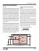
To calculate actual peak switch current with a given set
of conditions, use:
II
I
VVVVV
LfV
SW PEAK
OUT
P
OUT
OUT F IN OUT F
IN
()
=+
=+
+−
()
()()( )
I
2
L-P
() –
2
Reduced Inductor Value and Discontinuous Mode
If the smallest inductor value is of most importance to a
converter design, in order to reduce inductor size/cost,
discontinuous mode may yield the smallest inductor solu-
tion. The maximum output load current in discontinuous
mode, however, must be calculated and is defi ned later
in this section.
*Patent # 6, 498, 466