
Datasheet


10
LT1769
1769fa
APPLICATIONS INFORMATION
WUU
U
V
UV
= Rising lockout threshold on the UV pin
V
IN
= Charger input voltage that will sustain full load power
Example: With R6 = 5k, V
UV
= 6.7V and setting V
IN
at 12V;
R5 = 5k (12V – 6.7V)/6.7V = 4k
The resistor divider should be connected directly to the
adapter output as shown, not to the V
CC
pin, to prevent
battery drain with no adapter voltage. If the UV pin is not
used, connect it to the adapter output (not V
CC
) and
connect a resistor no greater than 5k to ground. Floating
this pin will cause reverse battery current to increase from
3µA to 200µA.
If connecting the unused UV pin to the adapter output is not
possible, it can be grounded. Although it would seem that
grounding the pin creates a permanent lockout state, the
UV circuitry is arranged for phase reversal with low volt-
ages on the UV pin to allow the grounding technique to work.
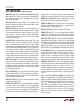
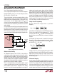
adapter load current remains below the limit. Amplifier
CL1 in Figure 2 senses the voltage across R
S4
, connected
between the CLP and CLN pins. When this voltage exceeds
100mV, the amplifier will override the programmed charge
current to limit adapter current to 100mV/R
S4
. A lowpass
filter formed by 500Ω and 1µF is required to eliminate
switching noise. If the input current limit is not used, both
CLP and CLN pins should be connected to V
CC
.
Charge Current Programming
The basic formula for charge current is (see Block
Diagram):
I
BAT
= I
PROG
=
2.465V
R
PROG
R
S2
R
S1
()()
R
S2
R
S1
()
where R
PROG
is the total resistance from PROG pin to ground.
For the sense amplifier CA1 biasing purpose, R
S3
should
have the same value as R
S2
and SPIN should be connected
directly to the sense resistor (R
S1
) as shown in the Block
Diagram.
For example, 2A charge current is needed. For low power
dissipation on R
S1
and enough signal to drive the amplifier
CA1, let R
S1
= 100mV/2A = 0.05Ω. This limits R
S1
power
to 0.2W. Let R
PROG
= 5k, then:
R
S2
= R
S3
=
= = 200Ω
(I
BAT
)(R
PROG
)(R
S1
)
2.465V
(2A)(5k)(0.05)
2.465V
Charge current can also be programmed by pulse width
modulating I
PROG
with a switch Q1 to R
PROG
at a frequency
higher than a few kHz (Figure 3). Charge current will be
proportional to the duty cycle of the switch with full current
at 100% duty cycle.
Lithium-Ion Charging
The 2A Lithium-Ion Battery Charger (Figure 1) charges at
a constant 2A until battery voltage reaches a limit set by R3
and R4. The charger will then automatically go into a
constant-voltage mode with current decreasing to near
zero over time as the battery reaches full charge. This is the
normal regimen for lithium-ion charging, with the charger
100mV
500Ω
CLP
CLN
V
CC
UV
1769 F02
R5
LT1769
R6
1µF
+
R
S4
*
V
IN
AC ADAPTER
OUTPUT
*R
S4
=
100mV
ADAPTER CURRENT LIMIT
+
–
+
CL1
Figure 2. Adapter Input Current Limiting
Adapter Current Limiting
An important feature of the LT1769 is the ability to
automatically adjust charge current to a level which avoids
overloading the wall adapter. This allows the product to
operate at the same time the batteries are being charged
without complex load management algorithms. Addition-
ally, batteries will automatically be charged at the maximum
possible rate of which the adapter is capable.
This is accomplished by sensing total adapter output
current and adjusting the charge current downward if a
preset adapter current limit is exceeded. True analog
control is used, with closed-loop feedback ensuring that