
Datasheet


13
LT1769
1769fa
APPLICATIONS INFORMATION
WUU
U
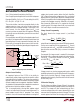
Figure 7. Lower V
BOOST
SW
BOOST
SPIN
1769 F07
LT1769
V
X
I
VX
C2
D2
10µF
L1
+
thermal resistance of the package-board combination is
dominated by the characteristics of the board in the
immediate area of the package. This means both lateral
thermal resistance across the board and vertical thermal
resistance through the board to other copper layers. Each
layer acts as a thermal heat spreader that increases the
heat sinking effectiveness of extended areas of the board.
Total board area becomes an important factor when the
area of the board drops below about 20 square inches. The
graph in Figure 8 shows thermal resistance vs board area
for 2-layer and 4-layer boards with continuous copper
planes. Note that 4-layer boards have significantly lower
thermal resistance, but both types show a rapid increase
for reduced board areas. Figure 9 shows actual measured
lead temperatures for chargers operating at full current.
Battery voltage and input voltage will affect device power
dissipation, so the data sheet power calculations must be
used to extrapolate these readings to other situations.
Vias should be used to connect board layers together.
Planes under the charger area can be cut away from the
rest of the board and connected with vias to form both a
low thermal resistance system and to act as a ground plane
for reduced EMI.
Glue-on, chip-mounted heat sinks are effective only in
moderate power applications where the PC board copper
cannot be used, or where the board size is small. They offer
very little improvement in a properly laid out multilayer
board of reasonable size.
Higher Duty Cycle for the LT1769 Battery Charger
Maximum duty cycle for the LT1769 is typically 90%, but
this may be too low for some applications. For example, if
Example: V
IN
= 19V, V
BAT
= 12.6V, I
BAT
= 2A:
P 3.5mA 19 1.5mA 12.6
12.6
19
7.5mA 0.012 2000mA 0.35W
P
2 12.6
55 19
0.43W
P
2 0.16 12.6
19
10 19 2 200kHz
0.42 0.08 0.5W
BIAS
2
DRIVER
2
SW
2
9
=
()()
+
()
+
()
+
()( )
[]
=
=
()( )
+
()
=
=
()( )( )
+
()()( )
=+=
−
1
12 6
30
.
Total Power in the IC is: 0.35 + 0.43 + 0.5 = 1.3W
Temperature rise will be (1.3W)(35°C/W) = 46°C. This
assumes that the LT1769 is properly heat sunk by con-
necting the eleven fused ground pins to expanded traces
and that the PC board has a backside or internal plane for
heat spreading.
The P
DRIVER
term can be reduced by connecting the boost
diode D2 (see Figure 7) to a lower system voltage (lower
than V
BAT
) instead of V
BAT
.
Then P
DRIVER
=
()( )()
+
()
IVV
V
V
BAT BAT X
X
IN
1
30
55
For example, V
X
= 3.3V then:
P
AVV
V
V
W
DRIVER
=
()( )( )
+
()
=
2 126 33 1
33
30
55 19
009
..
.
.
The average I
VX
required is:
P
V
W
V
mA
DRIVER
X
==
009
33
28
.
.
The previous example shows the dramatic drop in driver
power dissipation when the boost diode (D2) is connected
to an external 3.3V source instead of the 12.6V battery.
P
DRIVER
drops from 0.43W to 0.09W resulting in an
approximately 12°C drop in junction temperature.
Fused-lead packages conduct most of their heat out the
leads. This makes it very important to provide as much PC
board copper around the leads as is practical. Total