
Datasheet


15
LT1769
1769fa
APPLICATIONS INFORMATION
WUU
U
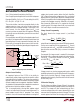
Optional Diode Connections
The typical application in Figure 1 shows a single diode
(D3) to isolate the V
CC
pin from the adaptor input and to
block reverse input voltage (both steady state and tran-
sient). This simple connection may be unacceptable in
situations where the system load must be powered from
the battery when the adapter input power is removed. As
shown in Figure 12, a parasitic diode exists from the SW
pin to the V
CC
pin in the LT1769. When the input power is
removed, this diode will become forward biased and will
provide a current path from the battery to the system load.
Because of diode power limitations, it is not recommended
to power the system load through the internal parasitic
diode. To safely power the system load from the battery,
an additional Schottky diode (D4) is needed. For minimum
losses, D4 could be replaced by a low R
DS(ON)
MOSFET
which is turned on when the adapter power is removed.
Layout Considerations
Switch rise and fall times are under 10ns for maximum
efficiency. To minimize radiation, the catch diode, SW pin
and input bypass capacitor leads should be kept as short
as possible. A ground plane should be used under the
switching circuitry to prevent interplane coupling and to
act as a thermal spreading path. All ground pins should be
connected to expanded traces for low thermal resistance.
The fast-switching high current ground path, including the
switch, catch diode and input capacitor, should be kept
very short. Catch diode and input capacitor should be
close to the chip and terminated to the same point. This
path contains nanosecond rise and fall times with several
amps of current. The other paths contain only DC and/or
200kHz tri-wave and are less critical. Figure 13 indicates
the high speed, high current switching path. Figure 14
shows critical path layout. Contact Linear Technology for
the LT1769 circuit PCB layout or Gerber file.
SW
L1
CLP
CLN
ADAPTER
IN
TO
SYSTEM
LOAD
R
S1
C
IN
R
S4
R7
500Ω
C1
1µF
D3
LT1769
INTERNAL
PARASITIC
DIODE
V
CC
1769 F12a
D4
+
+
+
Figure 12. Modified Diode Connection Figure 13. High Speed Switching Path
1769 F13
V
BAT
L1
V
IN
HIGH
FREQUENCY
CIRCULATING
PATH
BAT
SWITCH NODE
C
IN
C
OUT
D1
Information furnished by Linear Technology Corporation is believed to be accurate and reliable.
However, no responsibility is assumed for its use. Linear Technology Corporation makes no represen-
tation that the interconnection of its circuits as described herein will not infringe on existing patent rights.
C
IN
C
OUT
R
S1
D1
L1
GND
GND
1769 F14
TO
GND
TO
GND
NOTE: CONNECT ALL GND PINS TO EXPANDED PC LANDS FOR PROPER HEAT SINKING
GND
GND
GND
SW
BOOST
UV
GND
GND
OVP
CLP
CLN
COMP1
SENSE
GND
GND
GND
GND
V
CC1
V
CC2
V
CC3
GND
PROG
V
C
UV
OUT
COMP2
BAT
SPIN
GND
Figure 14. Critical Electrical and Thermal Path Layout