
Datasheet

LT1790
10
1790fb
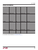
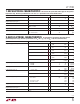
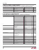
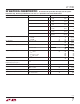
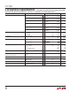
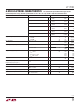
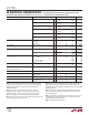
5V ELECTRICAL CHARACTERISTICS
The l denotes the specifi cations which apply over the specifi ed
temperature range, otherwise specifi cations are at T
A
= 25°C. C
L
= 1μF and V
IN
= 5.5V, unless otherwise noted.
PARAMETER CONDITIONS MIN TYP MAX UNITS
Output Voltage (Notes 3, 4) LT1790A 4.9975
–0.05
5 5.0025
0.05
V
%
LT1790B 4.995
–0.10
5 5.005
0.10
V
%
LT1790AC
l
l
4.99400
–0.120
5 5.00600
0.120
V
%
LT1790AI
l
l
4.99125
–0.175
5 5.00875
0.175
V
%
LT1790BC
l
l
4.98625
–0.275
5 5.01375
0.275
V
%
LT1790BI
l
l
4.97938
–0.4125
5 5.02063
0.4125
V
%
Output Voltage Temperature Coeffi cient (Note 5) T
MIN
≤ T
A
≤ T
MAX
LT1790A
LT1790B
l
l
5
12
10
25
ppm/°C
ppm/°C
Line Regulation 5.5V ≤ V
IN
≤ 18V
l
50 170
220
ppm/V
ppm/V
Load Regulation (Note 6) I
OUT
Source = 5mA
l
80 160
250
ppm/mA
ppm/mA
I
OUT
Sink = 3mA
l
70 110
300
ppm/mA
ppm/mA
Dropout Voltage (Note 7) V
IN
– V
OUT
, ΔV
OUT
= 0.1%
I
OUT
= 0mA
I
OUT
Source = 5mA
I
OUT
Sink = 3mA
l
l
l
50 100
120
450
250
mV
mV
mV
mV
Supply Current No Load
l
35 60
80
μA
μA
Minimum Operating Current—
Negative Output (See Figure 7)
V
OUT
= –5V, 0.1% 100 125 μA
Turn-On Time C
LOAD
= 1μF 700 μs
Output Noise (Note 8) 0.1Hz ≤ f ≤ 10Hz
10Hz ≤ f ≤ 1kHz
80
118
μV
P-P
μV
RMS
Long-Term Drift of Output Voltage (Note 9) 50 ppm/√kHr
Hysteresis (Note 10) ΔT = 0°C to 70°C
ΔT = –40°C to 85°C
l
l
25
40
ppm
ppm
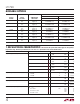
Note 1: Stresses beyond those listed under Absolute Maximum Ratings
may cause permanent damage to the device. Exposure to any Absolute
Maximum Rating condition for extended periods may affect device
reliability and lifetime.
Note 2: The LT1790 is guaranteed functional over the operating
temperature range of –40°C to 125°C. The LT1790-1.25 at 125°C is
typically less than 2% above the nominal voltage. The other voltage
options are typically less than 0.25% above their nominal voltage.
Note 3: If the part is stored outside of the specifi ed temperature range, the
output voltage may shift due to hysteresis.
Note 4: ESD (Electrostatic Discharge) sensitive device. Extensive use of
ESD protection devices are used internal to the LT1790, however, high
electrostatic discharge can damage or degrade the device. Use proper ESD
handling precautions.
Note 5: Temperature coeffi cient is measured by dividing the change in
output voltage by the specifi ed temperature range. Incremental slope is
also measured at 25°C.
Note 6: Load regulation is measured on a pulse basis from no load to the
specifi ed load current. Output changes due to die temperature change
must be taken into account separately.
Note 7: Excludes load regulation errors.