
Datasheet


4
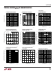
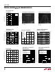
LT1792
E
LECTR
IC
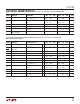
AL C CHARA TERIST
ICS
The ● denotes specifications which apply over the temperature range
–40°C ≤ T
A
≤ 85°C. V
S
=
±
15V, V
CM
= 0V, unless otherwise noted. (Notes 8, 9)
SYMBOL PARAMETER CONDITIONS (Note 2) MIN TYP MAX MIN TYP MAX UNITS
V
OS
Input Offset Voltage ● 0.5 1.0 1.2 3.7 mV
V
S
= ±5V ● 0.8 1.4 1.5 4.2 mV
∆V
OS
Average Input Offset (Note 6) ● 410 740 µV/°C
∆Temp
Voltage Drift
I
OS
Input Offset Current ● 300 800 300 800 pA
I
B
Input Bias Current ● 1200 4000 1200 4000 pA
V
CM
Input Voltage Range ● 12.6 13.0 12.6 13.0 V
● –10.0 –10.5 –10.0 –10.5 V
CMRR Common Mode Rejection Ratio V
CM
= –10V to 12.6V ● 80 103 78 98 dB
PSRR Power Supply Rejection Ratio V
S
= ±4.5V to ±20V ● 83 98 79 96 dB
A
VOL
Large-Signal Voltage Gain V
O
= ±12V, R
L
= 10k ● 850 3300 750 3000 V/mV
V
O
= ±10V, R
L
= 1k ● 400 2200 300 2000 V/mV
V
OUT
Output Voltage Swing R
L
= 10k ● ±12.8 ±13.1 ±12.8 ±13.1 V
R
L
= 1k ● ±11.8 ±12.1 ±11.8 ±12.1 V
SR Slew Rate R
L
≥ 2k ● 2.0 3.0 2.0 3.0 V/µs
GBW Gain-Bandwidth Product f
O
= 100kHz ● 2.9 4.3 2.9 4.3 MHz
I
S
Supply Current ● 4.2 5.40 4.2 5.40 mA
V
S
= ±5V ● 4.2 5.35 4.2 5.35 mA
Note 6: This parameter is not 100% tested.
Note 7: Slew rate is measured in A
V
= –1; input signal is ±7.5V, output
measured at ±2.5V.
Note 8: The LT1792AC and LT1792C are guaranteed to meet specified
performance from 0°C to 70°C and are designed, characterized and
expected to meet these extended temperature limits, but are not tested at
–40°C and 85°C. The LT1792I is guaranteed to meet the extended
temperature limits. The LT1792AC and LT1792AI grade are 100%
temperature tested for the specified temperature range.
Note 9: The LT1792 is measured in an automated tester in less than one
second after application of power. Depending on the package used,
power dissipation, heat sinking, and air flow conditions, the fully
warmed-up chip temperature can be 10°C to 50°C higher than the
ambient temperature.
Note 1: Absolute Maximum Ratings are those values beyond which the
life of a device may be impaired.
Note 2: Typical parameters are defined as the 60% yield of parameter
distributions of individual amplifiers.
Note 3: Warmed-up I
B
and I
OS
readings are extrapolated to a chip
temperature of 32°C from 25°C measurements and 32°C characterization
data.
Note 4: Current noise is calculated from the formula:
i
n
= (2qI
B
)
1/2
where q = 1.6 • 10
–19
coulomb. The noise of source resistors up to 200M
swamps the contribution of current noise.
Note 5: Input voltage range functionality is assured by testing offset
voltage at the input voltage range limits to a maximum of 2.3mV
(A grade), to 2.8mV (C grade).
LT1792AC/LT1792AI LT1792C/LT1792I