
Datasheet

8
LT1794
outputs are in a high impedance state. Part to part varia-
tions however, will cause inconsistent control of the qui-
escent current if direct voltage drive of the SHDN pin is used.
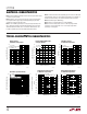
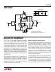
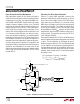
Using a single external resistor, R
BIAS
, connected in one of
two ways provides a much more predictable control of the
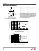
quiescent supply current. Figure 2 illustrates the effect on
supply current per amplifier with R
BIAS
connected be-
tween the SHDN pin and the 12V V
+
supply of the LT1794
and the approximate design equations. Figure 3 illustrates
the same control with R
BIAS
connected between the
SHDNREF pin and ground while the SHDN pin is tied to V
+
.
Either approach is equally effective.
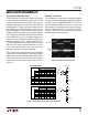
APPLICATIO S I FOR ATIO
WUUU
Figure 1. Internal Current Biasing Circuitry
2k
SHDN
SHDNREF
TO
START-UP
CIRCUITRY
1k
1794 F01
I
BIAS
TO AMPLIFIERS
BIAS CIRCUITRY
2I
I
2I
5I
2
5
I
BIAS
=
I
SUPPLY
PER AMPLIFIER (mA) = 64 • I
BIAS
I
SHDN
= I
SHDNREF
R
BIAS
(kΩ)
0
I
SUPPLY
PER AMPLIFIER (mA)
10
20
30
5
15
25
10
1794 F02
7 40 70 100 130 160 190
V
S
= ±12V
V
+
= 12V
R
BIAS
SHDN
SHDNREF
R
BIAS
=
• 25.6 – 2k
V
+
– 1.2V
I
S
PER AMPLIFIER (mA)
I
S
PER AMPLIFIER
(mA)
• 25.6
V
+
– 1.2V
R
BIAS
+ 2k
≈
R
BIAS
(kΩ)
4 7 10 50 90 130 170 210 25030 70 100 150 190 230 270 290
I
SUPPLY
PER AMPLIFIER (mA)
20
25
30
35
40
1794 F03
5
10
15
0
45
V
S
= ±12V
V
+
= 12V
R
BIAS
SHDN
SHDNREF
R
BIAS
=
• 64 – 5k
V
+
– 1.2V
I
S
PER AMPLIFIER (mA)
I
S
PER AMPLIFIER
(mA)
• 64
V
+
– 1.2V
R
BIAS
+ 5k
≈
Figure 2. R
BIAS
to V
+
Current Control
Figure 3. R
BIAS
to Ground Current Control