
Datasheet

9
LT1794
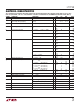
Two Control Inputs
RESISTOR VALUES (kΩ)
R
SHDN
TO V
CC
(12V) R
SHDN
TO V
LOGIC
V
LOGIC
R
SHDN
R
C1
R
CO
3V
40.2
11.5
19.1
3.3V
43.2
13.0
22.1
5V
60.4
21.5
36.5
3V
4.99
8.66
14.3
3.3V
6.81
10.7
17.8
5V
19.6
20.5
34.0
V
C0
H
L
H
L
V
C1
H
H
L
L
10
7
5
2
10
7
5
2
10
7
5
2
10
7
5
2
10
7
5
2
10
7
5
2
SUPPLY CURRENT PER AMPLIFIER (mA)
One Control Input
RESISTOR VALUES (kΩ)
R
SHDN
TO V
CC
(12V) R
SHDN
TO V
LOGIC
V
LOGIC
R
SHDN
R
C
3V
40.2
7.32
3.3V
43.2
8.25
5V
60.4
13.7
3V
4.99
5.49
3.3V
6.81
6.65
5V
19.6
12.7
V
C
H
L
10
2
10
2
10
2
10
2
10
2
10
2
SUPPLY CURRENT PER AMPLIFIER (mA)
R
SHDN
R
C1
V
C1
V
LOGIC
12V OR V
LOGIC
0V
V
C0
R
C0
SHDN
SHDNREF
2k
R
SHDN
R
C
V
C
V
LOGIC
12V OR V
LOGIC
0V
SHDN
SHDNREF
1794 F04
2k
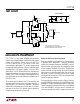
APPLICATIO S I FOR ATIO
WUUU
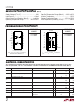
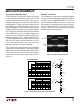
Logic Controlled Operating Current
The DSP controller in a typical xDSL application can have
I/O pins assigned to provide logic control of the LT1794
line driver operating current. As shown in Figure 4 one or
two logic control inputs can control two or four different
operating modes. The logic inputs add or subtract current
to the SHDN input to set the operating current. The one
logic input example selects the supply current to be either
full power, 10mA per amplifier or just 2mA per amplifier,
which significantly reduces the driver power consumption
while maintaining less than 2Ω output impedance to
frequencies less than 1MHz. This low power mode retains
termination impedance at the amplifier outputs and the
line driving back termination resistors. With this termina-
tion, while a DSL port is not transmitting data, it can still
sense a received signal from the line across the back-
termination resistors and respond accordingly.
The two logic input control provides two intermediate
(approximately 7mA per amplifier and 5mA per amplifier)
operating levels between full power and termination modes.
These modes can be useful for overall system power
management when full power transmissions are not
necessary.
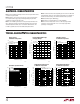
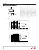
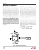
Shutdown and Recovery
The ultimate power saving action on a completely idle port
is to fully shut down the line driver by pulling the SHDN pin
to within 0.4V of the SHDNREF potential. As shown in
Figure 5 complete shutdown occurs in less than 10µs and,
more importantly, complete recovery from the shut down
state to full operation occurs in less than 2µs. The biasing
circuitry in the LT1794 reacts very quickly to bring the
amplifiers back to normal operation.
Figure 4. Providing Logic Input Control of Operating Current
V
SHDN
SHDNREF = 0V
AMPLIFIER
OUTPUT
1794 F05
Figure 5. Shutdown and Recovery Timing