
Datasheet


7
LT1930/LT1930A
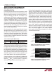
Figure 5. Transient Response of Step-Up Converter with 33µF
Tantalum Output Capacitor and No Phase Lead Capacitor
V
OUT
0.2V/DIV
AC COUPLED
I
LI
0.5A/DIV
AC COUPLED
250mA
150mA
LOAD
CURRENT
200µs/DIV
1930 F04
DIODE SELECTION
A Schottky diode is recommended for use with the LT1930/
LT1930A. The Motorola MBR0520 is a very good choice.
Where the switch voltage exceeds 20V, use the MBR0530
(a 30V diode). Where the switch voltage exceeds 30V, use
the MBR0540 (a 40V diode). These diodes are rated to
handle an average forward current of 0.5A. In applications
where the average forward current of the diode exceeds
0.5A, a Microsemi UPS5817 rated at 1A is recommended.
SETTING OUTPUT VOLTAGE
To set the output voltage, select the values of R1 and R2
(see Figure 1) according to the following equation.
RR
V
V
OUT
12
1 255
1=
.
–
A good value for R2 is 13.3k which sets the current in the
resistor divider chain to 1.255V/13.3k = 94.7µA.
Figure 6. Suggested Layout
R1
R2
GND
C3
C2
L1
D1 C1
V
OUT
V
IN
SHUTDOWN
1930 F06
+
+
GND
V
IN
SW
SHDN FB
V
IN
16V
4
51
3
D1
L1
2
R1
LT1930
1930 F07
C2
C1
121k
R2
V
OUT
Figure 7. Keeping SHDN Below 10V
LAYOUT HINTS
The high speed operation of the LT1930/LT1930A
demands careful attention to board layout. You will not get
advertised performance with careless layout. Figure 6
shows the recommended component placement.
Driving SHDN Above 10V
The maximum voltage allowed on the SHDN pin is 10V. If
you wish to use a higher voltage, you must place a resistor
in series with SHDN. A good value is 121k. Figure 7 shows
a circuit where V
IN
= 16V and SHDN is obtained from V
IN
.
The voltage on the SHDN pin is kept below 10V.
APPLICATIONS INFORMATION
WUU
U