
Datasheet


LT1941
1
1941fb
TYPICAL APPLICATION
DESCRIPTION
Triple Monolithic
Switching Regulator
The LT
®
1941 is a triple current mode DC/DC converter
with internal power switches. Two of the regulators are
step-down converters with 3A and 2A power switches.
The third regulator can be confi gured as a boost, inverter
or SEPIC converter and has a 1.5A power switch. All
three converters are synchronized to a 1.1MHz oscillator.
The two step-down converters run with opposite phase,
reducing input ripple current. The output voltages are
set with external resistor dividers and each regulator
has independent shutdown and soft-start circuits. Each
regulator generates a power good signal when its output
is in regulation, easing power supply sequencing and
interfacing with microcontrollers and DSPs.
The high switching frequency offers several advantages
by permitting the use of small inductors and ceramic
capacitors, leading to a very small triple output solution.
The constant switching frequency, combined with low
impedance ceramic capacitors, result in low, predictable
output ripple. With its wide input voltage range of 3.5V to
25V, the LT1941 regulates a broad array of power sources
from 4-cell batteries and 5V logic rails to unregulated wall
transformers, lead acid batteries and distributed-power
supplies.
L, LT, LTC and LTM are registered trademarks of Linear Technology Corporation. All other
trademarks are the property of their respective owners.
FEATURES
APPLICATIONS
n
Wide Input Range: 3.5V to 25V
n
Three Switching Regulators with Internal Power
Switches: 3A Step-Down, 2A Step-Down,
1.5A Inverting/Boost
n
Antiphase Switching Reduces Ripple
n
Independent Shutdown/Soft-Start Pins
n
Independent Power Good Indicators Ease Supply
Sequencing
n
Input Voltage Power Good Indicators Monitor Input
Supply
n
Uses Small Inductors and Ceramic Capacitors
n
Constant 1.1MHz Switching Frequency
n
Thermally Enhanced 28-Lead TSSOP Package
n
Cable Modems
n
DSL Modems
n
Distributed Power Regulation
n
Wall Transformer Regulation
n
Disk Drives
n
DSP Power
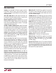
Figure 1. Triple Output Power Supply: 3.3V, 1.8V, –12V
Start-Up Waveforms
with Sequencing
V
OUT2
V
OUT1
LT1941
V
IN
GND
0.22μF
22μF
1000pF
1.5nF
1.5nF
3300pF
13.7k
133k
2.49k10k
V
IN
4.7V TO 14V
5GOOD
12GOOD
V
OUT1
1.8V
2.4A
V
OUT3
–12V
350mA*
3.3μH
3μH
22μH
22μH
10.7k
13.7k
7.32k 3.3k
1.5k
1941 F01
130k 100k 100k 100k 100k
PGOOD1
PGOOD2
PGOOD3
V
OUT2
3.3V
1.4A
0.22μF
33μF
1μF
10μF
*240mA AT V
IN
= 5V, 550mA AT V
IN
= 12V
10μF
22nF
PGOOD1
PGOOD2
PGOOD3
BOOST2
SW2
FB2
V
C2
SW1
FB1
V
C1
RUNSS2
BIAS1
BIAS2
V
C3
RUNSS3
RUNSS1
SW3
NFB
FB3
5GOOD
12GOOD
BOOST1
1.5nF
RUN/SS
2V/DIV
2ms/DIV
V
OUT1
2V/DIV
V
OUT2
5V/DIV
V
OUT3
10V/DIV
I
VIN(AVE)
1A/DIV
PGOOD2
5V/DIV
1941 F01b