
Datasheet


LT1952/LT1952-1
13
19521fe
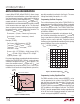
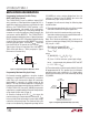
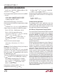
Shutdown and Programming Undervoltage Lockout
The LT1952/LT1952-1 have an accurate 1.32V shutdown
threshold at the SD_V
SEC
pin. This threshold can be
used in conjunction with a resistor divider to define the
undervoltage lockout threshold (UVLO) of the system
input voltage (V
S
) to the power converter (Figure 3). A pin
current hysteresis (10µA before part turn on, 0µA after
part turn on) allows UVLO hysteresis to be programmed.
Calculation of the ON/OFF thresholds for the supply (SV
IN
)
to the power converter can be made as follows:
V
S OFF
Threshold = 1.32[1 + (R1/R2)]
V
S ON
Threshold = SV
IN
OFF+(10µA•R1)
A simple open drain transistor can be added to the resistor
divider network at the SD_V
SEC
pin to control the turn off
of the LT1952/LT1952-1 (Figure 3).
The SD_V
SEC
pin must not be left open since there must
be an external source current >10µA to lift the pin past its
1.32V threshold for part turn on.
APPLICATIONS INFORMATION
Micropower Start-Up: Selection of Start-Up Resistor
and Capacitor for V
IN
The LT1952/LT1952-1 use turn-on voltage hysteresis at
the V
IN
pin and low start-up current to allow micro-power
start-up (Figure 4). The LT1952/LT1952-1 monitor V
IN
pin
voltage to allow part turn on at 14.25V (7.75V LT1952-1)
and part turn off at 8.75V (6.5V LT1952-1). Low start-up
OPERATION
Slope Compensation
The current mode architecture requires slope compensa-
tion to be added to the current sensing loop to prevent
subharmonic oscillations which can occur for duty cycles
above 50%. Unlike most current mode converters which
have a slope compensation ramp that is fixed internally,
placing a constraint on inductor value and operating
frequency, the LT1952/LT1952-1 have externally adjust-
able slope compensation. Slope compensation can be
programmed by inserting an external resistor (R
SLOPE
)
in series with the I
SENSE
pin. The LT1952/LT1952-1 have
a linear slope compensation ramp which sources current
out of the I
SENSE
pin of approximately 8µA at 0% duty
cycle to 35µA at 80% duty cycle.
Overcurrent Detection and Soft-Start (OC Pin)
An added feature to the LT1952/LT1952-1 is a precise
100mV sense threshold at the OC pin used to detect
overcurrent conditions in the converter and set a soft-start
latch. The OC pin is connected directly to the source of
the primary side MOSFET to monitor peak current in the
MOSFET (Figure 7). The 107mV threshold is constant
over the entire duty cycle range of the converter because
it is unaffected by the slope compensation added to the
I
SENSE
pin.
Synchronizing
A SYNC pin allows the LT1952/LT1952-1 oscillator to be
synchronized to an external clock. The SYNC pin can be
driven from a logic level output, requiring less than 0.8V
for a logic level low and greater than 2.2V for a logic level
high. Duty cycle should run between 10% and 90%. To
avoid loss of slope compensation during synchroniza-
tion, the free running oscillator frequency (f
OSC
) should
be programmed to 80% of the external clock frequency
(f
SYNC
). The R
SLOPE
resistor chosen for non-synchronized
operation should be increased by 1.25x (= f
SYNC
/f
OSC
).
Figure 3. Programming Undervoltage Lockout (UVLO)
1.32V
SYSTEM
INPUT (V
S
)
OPTIONAL
SHUTDOWN
TRANSISTOR
1952 F03
SD_V
SEC
11µA
LT1952/LT1952-1
R1
R2
+
–
OFFON