
Datasheet


LT1963A Series
17
1963aff
For more information www.linear.com/LT1963A
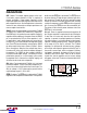
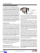
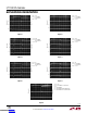
Y5V dielectrics are good for providing high capacitances in
a small package, but exhibit strong voltage and temperature
coefficients as shown in Figures 10 and 11. When used
with a 5V regulator, a 10µF Y5V capacitor can exhibit an
effective value as low as 1µF to 2µF over the operating
temperature range. The X5R and X7R dielectrics result in
more stable characteristics and are more suitable for use
as the output capacitor. The X7R type has better stability
across temperature, while the X5R is less expensive and
is available in higher values.
Voltage and temperature coefficients are not the only
sources of problems. Some ceramic capacitors have a
piezoelectric response. A piezoelectric device generates
voltage across its terminals due to mechanical stress,
similar to the way a piezoelectric accelerometer or micro-
phone works.
For a ceramic capacitor the stress can be
induced by vibrations in the system or thermal transients.
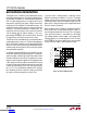
“FREE” Resistance with PC Traces
The resistance values shown in Table 2 can easily be made
using a small section of PC trace in series with the output
capacitor. The wide range of non-critical ESR makes it
easy to use PC trace. The trace width should be sized to
handle
the RMS ripple current associated with the load.
The output capacitor only sources or sinks current for a few
microseconds during fast output current transitions. There
is no DC current in the output capacitor. Worst case ripple
current will occur if the output load is a high frequency
(>100kHz) square wave with a high peak value and fast
edges (< 1µs). Measured RMS value for this case is 0.5
times the peak-to-peak current change. Slower edges or
lower frequency will significantly reduce the RMS ripple
current in the capacitor.
Figure 10. Ceramic Capacitor DC Bias Characteristics
DC BIAS VOLTAGE (V)
CHANGE IN VALUE (%)
1963A F10
20
0
–20
–40
–60
–80
–100
0
4
8
10
2 6
12
14
X5R
Y5V
16
BOTH CAPACITORS ARE 16V,
1210 CASE SIZE, 10µF
Figure 11. Ceramic Capacitor Temperature Characteristics
TEMPERATURE (°C)
–50
40
20
0
–20
–40
–60
–80
–100
25 75
1963A F11
–25 0
50 100 125
Y5V
CHANGE IN VALUE (%)
X5R
BOTH CAPACITORS ARE 16V,
1210 CASE SIZE, 10µF
applicaTions inForMaTion
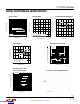
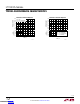
Table 2. PC Trace Resistors
10mΩ 20mΩ 30mΩ
0.5oz C
U
Width
Length
0.011
"
(0.28mm)
0.102
"
(2.6mm)
0.011
"
(0.28mm)
0.204
"
(5.2mm)
0.011
"
(0.28mm)
0.307
"
(7.8mm)
1.0oz C
U
Width
Length
0.006
"
(0.15mm)
0.110
"
(2.8mm)
0.006
"
(0.15mm)
0.220
"
(5.6mm)
0.006
"
(0.15mm)
0.330
"
(8.4mm)
2.0oz C
U
Width
Length
0.006
"
(0.15mm)
0.224
"
(5.7mm)
0.006
"
(0.15mm)
0.450
"
(11.4mm)
0.006
"
(0.15mm)
0.670
"
(17mm)
Downloaded from Arrow.com.Downloaded from Arrow.com.Downloaded from Arrow.com.Downloaded from Arrow.com.Downloaded from Arrow.com.Downloaded from Arrow.com.Downloaded from Arrow.com.Downloaded from Arrow.com.Downloaded from Arrow.com.Downloaded from Arrow.com.Downloaded from Arrow.com.Downloaded from Arrow.com.Downloaded from Arrow.com.Downloaded from Arrow.com.Downloaded from Arrow.com.Downloaded from Arrow.com.Downloaded from Arrow.com.