
Datasheet

LT3009 Series
13
3009fc
be implemented to prevent board contamination. If the
board is to be subjected to humidity cycling or if board
cleaning measures cannot be guaranteed, consideration
should be given to using resistors an order of magnitude
smaller than in Table 1 to prevent contamination from
causing unwanted shifts in the output voltage.
Output Capacitance and Transient Response
The LT3009 is stable with a wide range of output capaci-
tors. The ESR of the output capacitor affects stability, most
notably with small capacitors. Use a minimum output
capacitor of 1μF with an ESR of 3Ω or less to prevent os-
cillations. The LT3009 is a micropower device and output
load transient response is a function of output capacitance.
Larger values of output capacitance decrease the peak
deviations and provide improved transient response for
larger load current changes.
Give extra consideration to the use of ceramic capacitors.
Manufacturers make ceramic capacitors with a variety of
dielectrics, each with different behavior across tempera-
ture and applied voltage. The most common dielectrics
APPLICATIONS INFORMATION
DC BIAS VOLTAGE (V)
CHANGE IN VALUE (%)
3009 F02
20
0
–20
–40
–60
–80
–100
0
4
8
10
26
12
14
X5R
Y5V
16
BOTH CAPACITORS ARE 16V,
1210 CASE SIZE, 10μF
TEMPERATURE (°C)
–50
40
20
0
–20
–40
–60
–80
–100
25 75
3009 F03
–25 0
50 100 125
Y5V
CHANGE IN VALUE (%)
X5R
BOTH CAPACITORS ARE 16V,
1210 CASE SIZE, 10μF
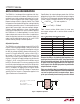
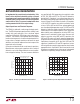
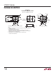
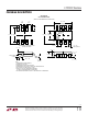
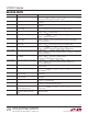
Figure 2. Ceramic Capacitor DC Bias Characteristics Figure 3. Ceramic Capacitor Temperature Characteristics
are specifi ed with EIA temperature characteristic codes
of Z5U, Y5V, X5R and X7R. The Z5U and Y5V dielectrics
provide high C-V products in a small package at low cost,
but exhibit strong voltage and temperature coeffi cients as
shown in Figures 2 and 3. When used with a 5V regulator,
a 16V 10μF Y5V capacitor can exhibit an effective value
as low as 1μF to 2μF for the DC bias voltage applied and
over the operating temperature range. The X5R and X7R
dielectrics yield more stable characteristics and are more
suitable for use as the output capacitor. The X7R type has
better stability across temperature, while the X5R is less
expensive and is available in higher values. One must still
exercise care when using X5R and X7R capacitors; the
X5R and X7R codes only specify operating temperature
range and maximum capacitance change over temperature.
Capacitance change due to DC bias with X5R and X7R
capacitors is better than Y5V and Z5U capacitors, but can
still be signifi cant enough to drop capacitor values below
appropriate levels. Capacitor DC bias characteristics tend
to improve as component case size increases, but expected
capacitance at operating voltage should be verifi ed.