
Datasheet


LT3010/LT3010-5
11
30105fe
APPLICATIONS INFORMATION
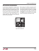
The thermal resistance junction-to-case (θ
JC
), measured
at the exposed pad on the back of the die, is 16°C/W.
Continuous operation at large input/output voltage dif-
ferentials and maximum load current is not practical
due to thermal limitations. Transient operation at high
input/output differentials is possible. The approximate
thermal time constant for a 2500sq mm 3/32" FR-4 board
with maximum topside and backside area for one ounce
copper is 3 seconds. This time constant will increase as
more thermal mass is added (i.e. vias, larger board, and
other components).
For an application with transient high power peaks, average
power dissipation can be used for junction temperature
calculations as long as the pulse period is significantly less
than the thermal time constant of the device and board.
Calculating Junction Temperature
Example 1: Given an output voltage of 5V, an input volt-
age range of 24V to 30V, an output current range of 0mA
to 50mA, and a maximum ambient temperature of 50°C,
what will the maximum junction temperature be?
The power dissipated by the device will be equal to:
I
OUT(MAX)
•(V
IN(MAX)
– V
OUT
) + (I
GND
•V
IN(MAX)
)
where:
I
OUT(MAX)
= 50mA
V
IN(MAX)
= 30V
I
GND
at (I
OUT
= 50mA, V
IN
= 30V) = 1mA
So:
P=50mA•(30V–5V)+(1mA•30V)=1.28W
The thermal resistance will be in the range of 40°C/W to
62°C/W depending on the copper area. So the junction
temperature rise above ambient will be approximately
equal to:
1.31W•50°C/W=65.5°C
The maximum junction temperature will then be equal to
the maximum junction temperature rise above ambient
plus the maximum ambient temperature or:
T
JMAX
= 50°C + 65.5°C = 115.5°C
Example 2: Given an output voltage of 5V, an input voltage
of 48V that rises to 72V for 5ms(max) out of every 100ms,
and a 5mA load that steps to 50mA for 50ms out of every
250ms, what is the junction temperature rise above ambi-
ent? Using a 500ms period (well under the time constant
of the board), power dissipation is as follows:
P1(48Vin,5mAload)=5mA•(48V–5V)
+(200µA•48V)=0.23W
P2(48Vin,50mAload)=50mA•(48V–5V)
+(1mA•48V)=2.20W
P3(72Vin,5mAload)=5mA•(72V–5V)
+(200µA•72V)=0.35W
P4(72Vin,50mAload)=50mA•(72V–5V)
+(1mA•72V)=3.42W
Operation at the different power levels is as follows:
76% operation at P1, 19% for P2, 4% for P3, and
1% for P4.
P
EFF
= 76%(0.23W) + 19%(2.20W) + 4%(0.35W)
+ 1%(3.42W) = 0.64W
With a thermal resistance in the range of 40°C/W to
62°C/W, this translates to a junction temperature rise above
ambient of 26°C to 38°C.
High Temperature Operation
Care must be taken when designing LT3010H applications to
operate at high ambient temperatures. The LT3010H works
at elevated temperatures but erratic operation can occur
due to unforeseen variations in external components. Some
tantalum capacitors are available for high temperature
operation, but ESR is often several ohms; capacitor ESR