
Datasheet

LT3071
16
3071fc
For more information www.linear.com/LT3071
APPLICATIONS INFORMATION
FPGA and ASIC processors are sufficient to stabilize the
system (see Stability and Output Capacitance section). This
regulator design provides ample bandwidth and responds
to transient load changes in a few hundred nanoseconds
versus regulators that respond in many microseconds.
The LT3071 also incorporates precision current limit
-
ing, enable/disable control of output voltage and inte-
grated overvoltage and thermal shutdown protection.
The
LT3071’s unique design combines the benefits of
low dropout voltage, high functional integration, precision
performance and UltraFast transient response, as well as
providing significant cost savings on the output capacitance
needed in fast load transient applications.
As lower voltage applications become increasingly preva
-
lent with higher frequency switching power supplies, the
LT3071
offers superior regulation and an appreciable
component cost savings. The LT3071 steps to the next
level of performance for the latest generation FPGAs, DSPs
and microprocessors. The simple versatility and benefits
derived from these circuits exceed the power supply needs
of today’s high performance microprocessors.
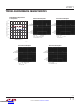
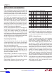
Programming Output Voltage
Three tri-level input pins, V
O2
, V
O1
and V
O0
, select the
value of output voltage. Table 1 illustrates the 3-bit digital
word to output voltage resulting from setting these
pins
high,
low or allowing them to float.
These pins may be tied high or low by either pin-strapping
them to V
BIAS
or driving them with digital ports. Pins that
float may either actually float or require logic that has
Hi-Z output capability. This allows output voltage to be
dynamically changed if necessary.
Output voltage is selectable from a minimum of 0.8V to
a maximum of 1.8V in increments of 50mV. The MSB,
V
O2
, sets the pedestal voltage, and the LSB’s, V
O1
and
V
O0
increment V
OUT
.
Output voltage is limited to 1.8V maximum by an internal
override of V
O1
(default to low) when V
O2
= high.
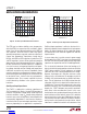
Table 1: V
O2
to V
O0
Settings vs Output Voltage
V
O2
V
O1
V
O0
V
OUT(NOM)
V
O2
V
O1
V
O0
V
OUT(NOM)
0 0 0 0.80V Z 0 1 1.35V
0 0 Z 0.85V Z Z 0 1.40V
0 0 1 0.90V Z Z Z 1.45V
0 Z 0 0.95V Z Z 1 1.50V
0 Z Z 1.00V Z 1 0 1.55V
0 Z 1 1.05V Z 1 Z 1.60V
0 1 0 1.10V Z 1 1 1.65V
0 1 Z 1.15V 1 X 0 1.70V
0 1 1 1.20V 1 X Z 1.75V
Z 0 0 1.25V 1 X 1 1.80V
Z 0 Z 1.30V
X = Don’t Care, 0 = Low, Z = Float, 1 = High
The input logic low threshold is less than 250mV refer-
enced to GND and the logic high
threshold is greater than
V
BIAS
– 250mV. The range between these two thresholds
as set by a window comparator defines the logic Hi-Z state.
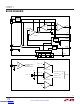
REF/BYP—Voltage Reference
This pin is the buffered output of the internal bandgap
reference and has an output impedance of ≅ 19kΩ. The
design includes an internal compensation pole at f
C
=
4kHz. A 10nF REF/BYP capacitor to GND creates a low-
pass pole
at f
LP
= 840Hz. The 10nF capacitor decreases
reference voltage noise to about 10µV
RMS
and soft-starts
the reference. The LT3071 only soft-starts the reference
voltage during
an initial turn-on sequence. If the EN pin
is
toggled low after initial turn-on, the reference remains
powered-up. Therefore, toggling the EN pin from low to
high does not soft-start the reference. Only by turning
the BIAS supply voltage on and off will the reference be
soft-started. Output voltage noise is the RMS sum of the
reference voltage noise in addition to the amplifier noise.
The REF/BYP pin must not be DC loaded by anything except
for applications that parallel other LT3071 regulators for
higher output currents. Consult the Applications section
on Paralleling for further details.
Downloaded from Arrow.com.Downloaded from Arrow.com.Downloaded from Arrow.com.Downloaded from Arrow.com.Downloaded from Arrow.com.Downloaded from Arrow.com.Downloaded from Arrow.com.Downloaded from Arrow.com.Downloaded from Arrow.com.Downloaded from Arrow.com.Downloaded from Arrow.com.Downloaded from Arrow.com.Downloaded from Arrow.com.Downloaded from Arrow.com.Downloaded from Arrow.com.Downloaded from Arrow.com.