
Datasheet
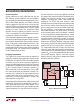
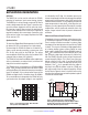
Table Of Contents
LT3480
13
3480fe
For more information www.linear.com/LT3480
APPLICATIONS INFORMATION
–
+
0.8V
SW
V
C
g
m
=
420µmho
GND
3M
LT3480
3480 F02
R1
OUTPUT
ESR
C
F
C
C
R
C
ERROR
AMPLIFIER
FB
R2
C1
C1
CURRENT MODE
POWER STAGE
g
m
= 3.5mho
+
POLYMER
OR
TANTALUM
CERAMIC
C
PL
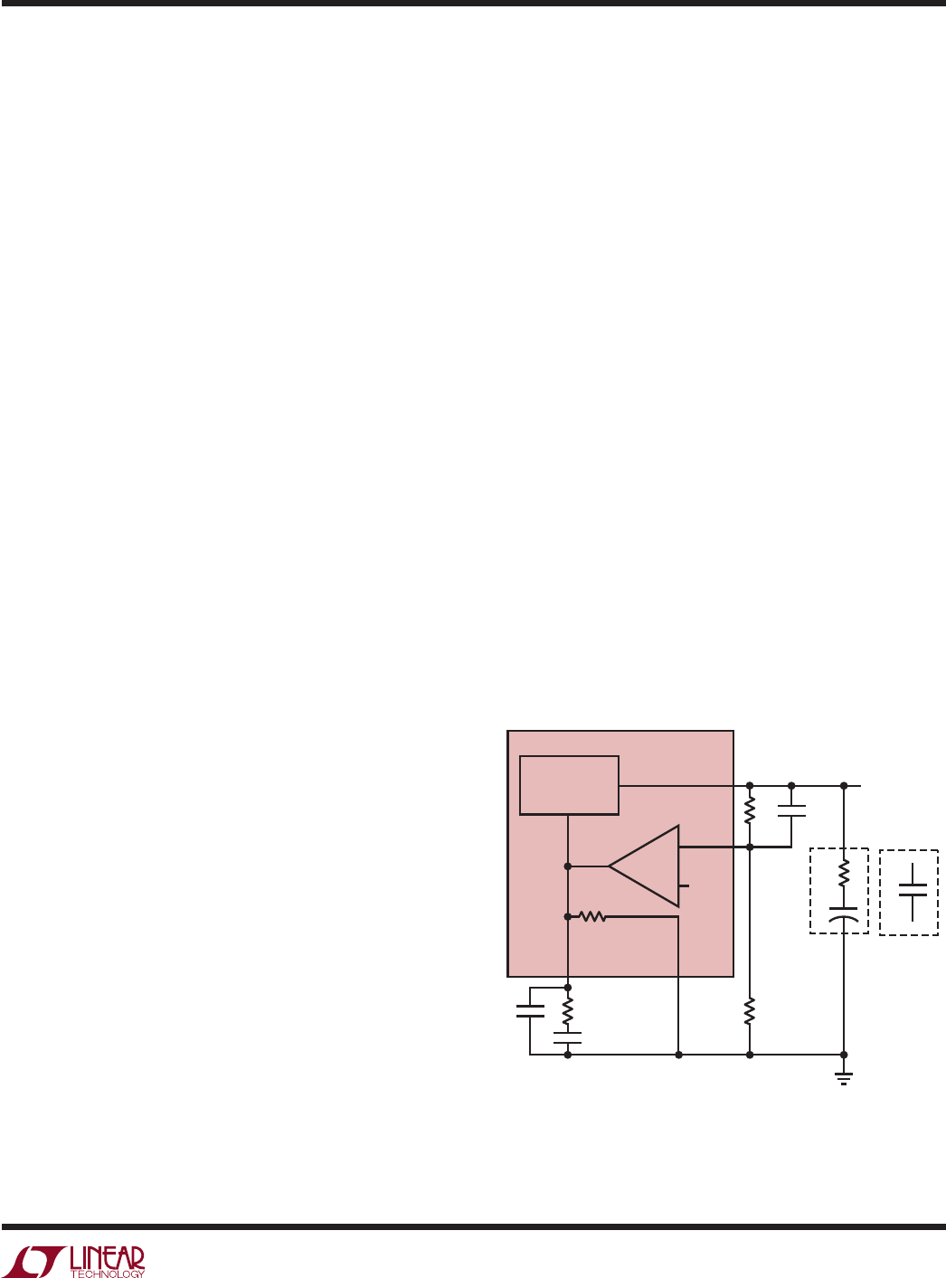
Figure 2. Model for Loop Response
Ceramic Capacitors
Ceramic capacitors are small, robust and have very low
ESR. However, ceramic capacitors can cause problems
when used with the LT3480 due to their piezoelectric nature.
When in Burst Mode operation, the LT3480’s switching
frequency depends on the load current, and at very light
loads the LT3480 can excite the ceramic capacitor at audio
frequencies, generating audible noise. Since the LT3480
operates at a lower current limit during Burst Mode
operation, the noise is typically very quiet to a casual ear.
If this is unacceptable, use a high performance tantalum
or electrolytic capacitor at the output.
A final precaution regarding ceramic capacitors concerns
the maximum input voltage rating of the LT3480. A ceramic
input capacitor combined with trace or cable inductance
forms a high quality (under damped) tank circuit. If the
LT3480 circuit is plugged into a live supply, the input volt-
age can ring to twice its nominal value, possibly exceeding
the LT3480’s rating. This situation is easily avoided (see
the Hot Plugging Safely section).
Frequency Compensation
The LT3480 uses current mode control to regulate the
output. This simplifies loop compensation. In particular, the
LT3480 does not require the ESR of the output capacitor
for stability, so you are free to use ceramic capacitors to
achieve low output ripple and small circuit size. Frequency
compensation is provided by the components tied to the
V
C
pin, as shown in Figure 2. Generally a capacitor (C
C
)
and a resistor (R
C
) in series to ground are used. In addi-
tion, there may be lower value capacitor in parallel. This
capacitor (C
F
) is not part of the loop compensation but
is used to filter noise at the switching frequency, and is
required only if a phase-lead capacitor is used or if the
output capacitor has high ESR.
Loop compensation determines the stability and transient
performance. Designing the compensation network is
a bit complicated and the best values depend on the
application and in particular the type of output capacitor.
A practical approach is to start with one of the circuits in
this data sheet that is similar to your application and tune
the compensation network to optimize the performance.
Stability should then be checked across all operating
conditions, including load current, input voltage and
temperature. The LT1375 data sheet contains a more
thorough discussion of loop compensation and describes
how to test the stability using a transient load. Figure 2
shows an equivalent circuit for the LT3480 control loop.
The error amplifier is a transconductance amplifier with
finite output impedance. The power section, consisting
of the modulator, power switch and inductor, is modeled
as a transconductance amplifier generating an output
current proportional to the voltage at the V
C
pin. Note that
the output capacitor integrates this current, and that the
capacitor on the V
C
pin (C
C
) integrates the error amplifier
output current, resulting in two poles in the loop. In most
cases a zero is required and comes from either the output
capacitor ESR or from a resistor R
C
in series with C
C
.
This simple model works well as long as the value of the
inductor is not too high and the loop crossover frequency
is much lower than the switching frequency. A phase lead
capacitor (C
PL
) across the feedback divider may improve
the transient response. Figure 3 shows the transient
response when the load current is stepped from 500mA
to 1500mA and back to 500mA.