
Datasheet


LT3514
18
3514fa
For more information www.linear.com/LT3514
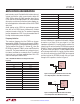
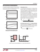
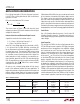
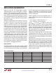
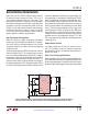
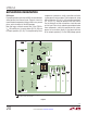
Figure 6 shows the transient response of the LT3514 with
several output capacitor choices. The output is 3.3V. The
load current is stepped from 500mA to 1A and back to
500mA and the oscilloscope traces show the output volt
-
age. The upper photo shows the recommended value. The
second photo shows the improved response (less voltage
drop) resulting from a larger output capacitor and a larger
phase lead capacitor
. The last photo shows the response
to a high performance electrolytic capacitor. Transient per
-
formance is improved due to the large output capacitance.
Shorted and Reversed Input Protection
If the inductor is chosen so that it won’t saturate exces-
sively, an LT3514 buck regulator will tolerate a shorted
output. There is another situation to consider in systems
where the output will be held high when the input to the
LT3514 is absent. This may occur in battery charging ap
-
plications or in battery backup systems where a battery
or some other supply is diode OR-ed with the LT3514’
s
output. If the V
IN
pin is allowed to float and the EN/UVLO
pin is held high (either by a logic signal or because it is
APPLICATIONS INFORMATION
Figure 6. Transient Load Response of the LT3514 with Different Output Capacitors as the
Load Current Is Stepped from 500mA to 1A. V
IN
= 12V, V
OUT
= 3.3V, L = 10µH, R
T
= 19.1k
10µF
31.6k
10k
I
OUT
1A/DIV
V
OUT
20mV/DIV
I
OUT
1A/DIV
V
OUT
20mV/DIV
20µs/DIV
20µs/DIV
I
OUT
1A/DIV
V
OUT
20mV/DIV
20µs/DIV
V
OUT
3514 F06a
3514 F06b
3514 F06c
V
OUT
31.6k
10k
10µF
×2
100pF
31.6k
10k
V
OUT
+
22µF
FB
LT3514
FB
LT3514
FB
LT3514