
Datasheet

LT3517
10
3517fg
For more information www.linear.com/LT3517
Table 1 provides some recommended inductor vendors.
Table 1. Inductor Manufacturers
VENDOR PHONE WEB
Sumida (408) 321-9660 www.sumida.com
Toko (408) 432-8281 www.toko.com
Cooper (561) 998-4100 www.cooperet.com
Vishay (402) 563-6866 www.vishay.com
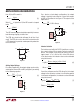
Input Capacitor Selection
For proper operation, it is necessary to place a bypass
capacitor to GND close to the V
IN
pin of the LT3517. A
1µF or greater capacitor with low ESR should be used. A
ceramic capacitor is usually the best choice.
In the buck mode configuration, the capacitor at the input
to the power converter has large pulsed currents due to
the current returned though the Schottky diode when the
switch is off. For best reliability, this capacitor should have
low ESR and ESL and have an adequate ripple current
rating. The RMS input current is:
I
IN(RMS)
= I
LED
• (1– D)• D
(8)
where D is the switch duty cycle. A 2.2µF ceramic type
capacitor is usually sufficient.
Output Capacitor Selection
The selection of output capacitor depends on the load
and converter configuration, i.e., step-up or step-down.
For LED applications, the equivalent resistance of the LED
is typically low, and the output filter capacitor should be
sized to attenuate the current ripple.
To achieve the same LED ripple current, the required filter
capacitor value is larger in the boost and buck-boost mode
applications than that in the buck mode applications. For
LED buck mode applications, a 1µF ceramic capacitor
is usually sufficient. For the LED boost and buck-boost
mode applications, a 2.2µF ceramic capacitor is usually
sufficient. Very high performance PWM dimming appli-
cations may require a larger capacitor value to support
the LED voltage during PWM transitions.
Use only ceramic capacitors with X7R, X5R or better dielec-
tric as they are best for temperature and DC bias stability
of the capacitor value. All ceramic capacitors exhibit loss
of capacitance value with increasing DC voltage bias, so it
may be necessary to choose a higher value capacitor to get
the required capacitance at the operation voltage. Always
check that the voltage rating of the capacitor is sufficient.
Table 2 shows some recommended capacitor vendors.
Table 2. Ceramic Capacitor Manufacturers
VENDOR PHONE WEB
Taiyo Yuden (408) 573-4150 www.t-yuden.com
AVX (843) 448-9411 www.avxcorp.com
Murata (770) 436-1300 www.murata.com
TDK (847) 803-6100 www.tdk.com
Loop Compensation
The LT3517 uses an internal transconductance error ampli-
fier whose VC output compensates the control loop. The
external inductor, output capacitor, and the compensa-
tion resistor and capacitor determine the loop stability.
The inductor and output capacitor are chosen based on
performance, size and cost. The compensation resistor
and capacitor at VC are selected to optimize control loop
stability. For typical LED applications, a 10nF compensation
capacitor at VC is adequate and a series resistor is not
required. A compensation resistor may be used to increase
the slew rate on the VC pin to maintain tighter regulation
of LED current during fast transients on V
IN
or CTRL.
Diode Selection
The Schottky diode conducts current during the interval
when the switch is turned off. Select a diode rated for
the maximum SW voltage. If using the PWM feature for
dimming, it is important to consider diode leakage, which
increases with the temperature, from the output during the
PWM low interval. Therefore, choose the Schottky diode
with sufficiently low leakage current. Table 3 has some
recommended component vendors.
APPLICATIONS INFORMATION