
Datasheet

LT3517
9
3517fg
For more information www.linear.com/LT3517
APPLICATIONS INFORMATION
than 1V, the LED current is:
I
LED
=
V
CTRL
10 • R
SENSE
(2)
When V
CTRL
is higher than 1V, the LED current is clamped
to be:
I
LED
=
100mV
R
SENSE
(3)
The LED current programming feature possibly increases
total dimming range by a factor of ten.
The CTRL pin should not be left open (tie to V
REF
if not
used). The CTRL pin can also be used in conjunction with
a PTC thermistor to provide overtemperature protection
for the LED load.
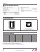
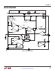
For a buck or a buck-boost configuration, the output
voltage is typically level-shifted to a signal with respect
to GND, as illustrated in the Figure 4. The output can be
expressed as:
V
OUT
=
R1
R2
• 1.01V + V
BE(Q1)
(5)
49.9k
3517 F02
45.3k
2V
V
REF
5k
PTC
CTRL
Figure 2
Setting Output Voltage
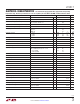
For a boost application, the output voltage can be set by
selecting the values of R1 and R2 (see Figure 3) according
to the following equation:
V
OUT
=
R1
R2
+ 1
• 1.01V
(4)
LT3517
FB
R1
V
OUT
R2
3517 F03
Figure 3
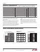
LT3517
FB
R1
Q2
+
–
LED
ARRAY
V
OUT
R2
3517 F04
R
SENSE
Figure 4
Inductor Selection
The inductor used with the LT3517 should have a satura-
tion current rating of 2A or greater. For buck mode LED
drivers, the inductor value should be chosen to give a
ripple current “ΔI” of ~30% to 40% of the LED current.
In the buck mode, the inductor value can be estimated
using the formula:
L µH
( )
=
D
BUCK
• t
SW
(µs) • V
IN
– V
LED
( )
ΔI
D
BUCK
=
V
LED
V
IN
(6)
V
LED
is the voltage across the LED string, V
IN
is the input
voltage to the converter, and t
SW
is the switching period.
In the boost configuration, the inductor can be estimated
using the formula:
L µH
( )
=
D
BOOST
• t
SW
(µs) • V
IN
ΔI
D
BOOST
=
V
LED
– V
IN
V
LED
(7)