
Datasheet


LT3591
10
3591f
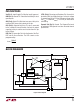
and ground as shown in Figure 6. A Si2308 MOSFET can
be used since its source is connected to ground. The PWM
signal is applied to the CTRL pin of the LT3591 and the gate
of the MOSFET. The PWM signal should traverse between
0V to 5V, to ensure proper turn on and off of the driver
and the NMOS transistor Q1. When the PWM signal goes
high, the LEDs are connected to ground and a current of
I
LED
= 200mV/R
SENSE
fl ows through the LEDs. When the
PWM signal goes low, the LEDs are disconnected and
turn off. The MOSFET ensures that the LEDs quickly turn
off without discharging the output capacitor which in turn
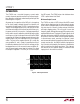
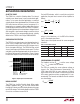
allows the LEDs to turn on faster. Figure 7 shows the PWM
dimming waveforms for the circuit in Figure 6.
APPLICATIONS INFORMATION
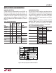
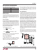
The calculations show that for a 100Hz signal the dimming
range is 83 to 1. In addition, the minimum PWM duty cycle
of 1.2% ensures that the LED current has enough time
to settle to its fi nal value. Figure 8 shows the dimming
range achievable for different frequencies with a settling
time of 120µs.
I
L
500mA/DIV
I
LED
20mA/DIV
PWM
5V/DIV
V
IN
= 3.6V
10 LEDs
2ms/DIV
3591 F07
Figure 7. Direct PWM Dimming Waveforms
The time it takes for the LED current to reach its pro-
grammed value sets the achievable dimming range for a
given PWM frequency. For example, the settling time of
the LED current in Figure 7 is approximately 120µs for a
3.6V input voltage. The achievable dimming range for this
application and 100Hz PWM frequency can be determined
using the following method.
Example:
ƒ
ƒ
==
== =
100 120
11
100
001
Hz t µs
ts
SETTLE
PERIOD
,
.
DDim Range
t
t
s
µs
Mi
PERIOD
SETTLE
.
:===
001
120
83 1
nn Duty Cycle
t
t
µs
s
SETTLE
PERIOD
•
.
==100
120
001
••.%
%.%
100 1 2
100 1 2 100
=
=→Duty Cycle Range at HHz
PWM DIMMING FREQUENCY (Hz)
10
PWM DIMMING RANGE
100
1000
10000
100 1000 10000
3591 F08
1
10
PULSING MAY BE VISIBLE
Figure 8. Dimming Range vs Frequency
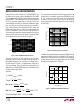
In addition to extending the dimming range, PWM dimming
improves the effi ciency of the converter for LED currents
below 20mA. Figure 9 shows the effi ciency for traditional
analog dimming of the front page application and PWM
dimming of the application in Figure 6.
Figure 9. PWM vs Analog Dimming Effi ciency
LED CURRENT (mA)
0
EFFICIENCY (%)
60
65
70
20
3591 F09
55
5
10
15
80
75
PWM DIMMING
ANALOG DIMMING
V
IN
= 3.6V
10 LEDs