
Datasheet


LT3591
9
3591f
APPLICATIONS INFORMATION
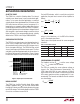
Table 4. R
SENSE
Value Selection for 200mV Sense
I
LED
(mA) R
SENSE
(Ω)
540
10 20
15 13.3
20 10
DIMMING CONTROL
There are three different types of dimming control circuits.
The LED current can be set by modulating the CTRL pin
with a DC voltage, a fi ltered PWM signal or directly with
a PWM signal.
Using a DC Voltage
For some applications, the preferred method of brightness
control is a variable DC voltage to adjust the LED current.
The CTRL pin voltage can be modulated to set the dim-
ming of the LED string. As the voltage on the CTRL pin
increases from 0V to 1.5V, the LED current increases from
0 to I
LED
. As the CTRL pin voltage increases beyond 1.5V,
it has no effect on the LED current.
The LED current can be set by:
I
mV
R
when V V
I
V
LED
SENSE
CTRL
LED
CTRL
≈>
≈
200
15
6
,.
.
225
125
•
,.
R
when V V
SENSE
CTRL
<
Feedback voltage variation versus control voltage is given
in the Typical Performance Characteristics.
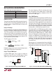
Using a Filtered PWM Signal
A fi ltered PWM signal can be used to control the
brightness of the LED string. The PWM signal is fi ltered
(Figure 5) by a RC network and fed to the CTRL pin.
The corner frequency of R1, C1 should be much lower
than the frequency of the PWM signal. R1 needs to be
much smaller than the internal impedance of the CTRL
pin which is 10MΩ (typ).
Direct PWM Dimming
Changing the forward current fl owing in the LEDs not only
changes the intensity of the LEDs, it also changes the color.
The chromaticity of the LEDs changes with the change in
forward current. Many applications cannot tolerate any
shift in the color of the LEDs. Controlling the intensity of
the LEDs with a direct PWM signal allows dimming of the
LEDs without changing the color. In addition, direct PWM
dimming offers a wider dimming range to the user.
Dimming the LEDs via a PWM signal essentially involves
turning the LEDs on and off at the PWM frequency. The
typical human eye has a limit of ~60 frames per second.
By increasing the PWM frequency to ~80Hz or higher,
the eye will interpret that the pulsed light source is con-
tinuously on. Additionally, by modulating the duty cycle
(amount of “on-time”), the intensity of the LEDs can be
controlled. The color of the LEDs remains unchanged in
this scheme since the LED current value is either zero or
a constant value.
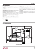
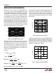
Figure 6 shows a Li-Ion powered driver for ten white LEDs.
Direct PWM dimming method requires an external NMOS
tied between the cathode of the lowest LED in the string
LT3591
CTRL
C1
0.1µF
PWM
10kHz TYP
3591 F05
R1
100k
Figure 5. Dimming Control Using a Filtered PWM Signal
CTRL
PWM
FREQ
V
IN
L1
22µH
V
IN
3V TO
5V
R
SENSE
10Ω
3591 F06
LT3591
SW
CAP
LED
100k
GND
0V
5V
C2
2.2µF
Q1
Si2308
C1
1µF
Figure 6. Li-Ion to Ten White LEDs with Direct PWM Dimming