
Datasheet


LT3748
14
3748fb
For more information www.linear.com/LT3748
applications inForMation
the output voltage multiplied by the windings ratio plus
some amount of overshoot caused by leakage inductance.
Second, increasing the turns ratio will increase the peak
current seen on the output diode generally increasing the
RMS diode current thereby lowering the efficiency. This
efficiency limitation is worse at lower output voltages when
the diode forward voltage is significant compared to the
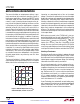
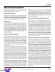
output voltage. In a typical application such as the 5V, 2A
output shown on the back page, the diode losses dominate
all the other losses, as shown in Figure 4. To calculate
RMS diode current, two equations are needed—the first
for calculating duty cycle, D, and the second to calculate
the RMS current of a triangle waveform:
D =
V
OUT
+ V
F(DODE)
( )
• N
PS
V
IN
+ V
OUT
+ V
F(DIODE)
( )
• N
PS
I
DIODE(RMS)
=
I
LIM
• N
PS
( )
2
• 1– D
( )
3
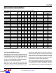
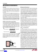
For a more general analysis, Figure 5 illustrates a sweep
of windings ratio on the x-axis while comparing output
power and estimated efficiency for a 5V output using a
48V input. If the desired application required 20W, the
maximum power curve indicates that a winding ratio of
12:1 would be sufficient at a current limit of 2A (R
SENSE
=
0.05Ω), while a winding ratio of 5:1 would deliver the same
power at 3A. However, when examining the corresponding
efficiency at max load for those two windings ratios and
current limits, the 5:1, 3A selection is clearly the superior
solution with an estimated efficiency of 85% compared to
78% for the 12:1, 2A application.
There are several caveats to this evaluation. First, as the
diode forward voltage becomes a smaller percentage of
total loss at higher output voltages (>12V) the RMS current
becomes less of a concern and minimizing it will have a
much smaller impact on efficiency. More significantly, if
a lower turns ratio forces the use of a diode with a larger
forward drop to obtain a higher reverse voltage rating,
any gains from minimizing current might be lost. For low
output voltages (3.3V or 5V) or high input voltages (>48V),
a turns ratio greater
than one can be used with multiple
primar
y windings relative to the secondary to maximize
the transformer’s current gain.
INPUT VOLTAGE (V)
0
OUTPUT POWER (W)
15
20
25
80
3748 F03
10
5
0
20
40
60
100
N
PS
= 2:1
I
LIM
= 3A
N
PS
= 3:1
I
LIM
= 2A
N
PS
= 6:1
I
LIM
= 1A
I
OUT
(A)
0.2A MIN
70
EFFICIENCY LOSS (%)
75
80
85
90
100
2A MAX
3748 F03
95
V
IN
= 12V
D
OUT
f
SW
• Q
G
+ I
Q
TRANSFORMER I • R + LEAKAGE
FET R
DS(ON)
N
PS
0
ESTIMATED MAX LOAD EFFICIENCY (%)
MAXIMUM OUTPUT POWER (W)
75
80
85
9
15
3748 F05
70
65
60
3 6 12
90
95
100
12
16
20
8
4
0
24
28
32
18
I
LIM
= 3A
I
LIM
= 2A
EFFICIENCY
OUTPUT
POWER
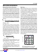
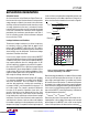
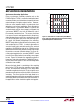
Figure 3. Maximum Output Power at 12V Out Using Three
Transformers with Equal Peak Output Current and Secondary
Inductance
Figure 4. Sources of Loss In 5V, 2A Out Typical Application
Figure 5. Estimated Efficiency and Output Power at 5V
OUT
from
48V
IN
vs Windings Ratio, N
PS
, at 2A and 3A Current Limits
Downloaded from Arrow.com.Downloaded from Arrow.com.Downloaded from Arrow.com.Downloaded from Arrow.com.Downloaded from Arrow.com.Downloaded from Arrow.com.Downloaded from Arrow.com.Downloaded from Arrow.com.Downloaded from Arrow.com.Downloaded from Arrow.com.Downloaded from Arrow.com.Downloaded from Arrow.com.Downloaded from Arrow.com.Downloaded from Arrow.com.