
Datasheet


LT3755/LT3755-1/LT3755-2
11
37551fd
applicaTions inForMaTion
INTV
CC
Regulator Bypassing and Operation
The INTV
CC
pin requires a capacitor for stable operation
and to store the charge for the large GATE switching cur-
rents. Choose a 10V rated low ESR, X7R or X5R ceramic
capacitor for best performance. A 4.7µF capacitor will be
adequate for many applications. Place the capacitor close
to the IC to minimize the trace length to the INTV
CC
pin
and also to the IC ground.
An internal current limit on the INTV
CC
output protects
the LT3755 from excessive on-chip power dissipation.
The minimum value of this current should be considered
when choosing the switching NMOS and the operating
frequency.
I
INTVCC
can be calculated from the following equation:
I
INTVCC
= Q
G
• f
OSC
Careful choice of a lower Q
G
FET will allow higher switch-
ing frequencies, leading to smaller magnetics. The INTV
CC
pin has its own undervoltage disable (UVLO) set to 4.1V
(typical) to protect the external FETs from excessive power
dissipation caused by not being fully enhanced. If the
INTV
CC
pin drops below the UVLO threshold, the GATE
and PWMOUT pins will be forced to 0V and the soft-start
pin will be reset.
If the input voltage, V
IN
, will not exceed 8V, then the IN-
TV
CC
pin could be connected to the input supply. Be aware
that a small current (less than 12μA) will load the INTV
CC
in shutdown. This action allows the LT3755 to operate
from V
IN
as low as 4.5V. If V
IN
is normally above, but
occasionally drops below the INTV
CC
regulation voltage,
then the minimum operating V
IN
will be close to 6V . This
value is determined by the dropout voltage of the linear
regulator and the INTV
CC
undervoltage lockout threshold
mentioned above.
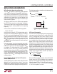
Programming the Turn-On and Turn-Off Thresholds
with the SHDN/UVLO Pin
The falling UVLO value can be accurately set by the resistor
divider. A small 2.1µA pull-down current is active when
SHDN/UVLO is below the threshold. The purpose of this
current is to allow the user to program the rising hysteresis.
SHDN/UVLO
LT3755
V
IN
R2
37551 F01
R1
Figure 1. Resistor Connection to Set
V
IN
Undervoltage Shutdown Threshold
The following equations should be used to determine the
values of the resistors:
V
IN,FALLING
=1.22 •
R1+R2
R2
V
IN,RISING
= 2.1µA •R1 + V
IN,FALLING
LED Current Programming
The LED current is programmed by placing an appropriate
value current sense resistor, R
LED
, in series with the LED
string. The voltage drop across R
LED
is (Kelvin) sensed
by the ISP and ISN pins. Typically, sensing of the current
should be done at the top of the LED string. If this option
is not available, then the current may be sensed at the
bottom of the string, but take caution that the minimum
ISN value does not fall below 3V, which is the lower limit of
the LED current regulation function. The CTRL pin should
be tied to a voltage higher than 1.2V to get the full-scale
100mV (typical) threshold across the sense resistor. The
CTRL pin can also be used to dim the LED current to zero,
although relative accuracy decreases with the decreasing
voltage sense threshold. When the CTRL pin voltage is
less than 1V, the LED current is:
I
LED
=
V
CTRL
− 100mV
R
LED
• 10
When the CTRL pin voltage is between 1V and 1.2V the LED
current varies with CTRL, but departs from the equation
above by an increasing amount as CTRL voltage increases.
Ultimately, above CTRL = 1.2V the LED current no longer
varies with CTRL. At CTRL = 1.1V, the actual value of I
LED
is ~98% of the equation’s estimate.