LT3757/LT3757A Boost, Flyback, SEPIC and Inverting Controller Features n n n n n n n n n n Description Wide Input Voltage Range: 2.9V to 40V Positive or Negative Output Voltage Programming with a Single Feedback Pin Current Mode Control Provides Excellent Transient Response Programmable Operating Frequency (100kHz to 1MHz) with One External Resistor Synchronizable to an External Clock Low Shutdown Current < 1µA Internal 7.
LT3757/LT3757A Absolute Maximum Ratings (Note 1) VIN, SHDN/UVLO (Note 6)..........................................40V INTVCC.....................................................VIN + 0.3V, 20V GATE......................................................... INTVCC + 0.3V SYNC...........................................................................8V VC , SS..........................................................................3V RT.........................................................................
LT3757/LT3757A Electrical Characteristics The l denotes the specifications which apply over the full operating temperature range, otherwise specifications are at TA = 25°C. VIN = 24V, SHDN/UVLO = 24V, SENSE = 0V, unless otherwise noted. PARAMETER CONDITIONS MIN VIN Operating Range TYP 2.9 MAX UNITS 40 V VIN Shutdown IQ SHDN/UVLO = 0V SHDN/UVLO = 1.15V 0.1 1 6 µA µA VIN Operating IQ VC = 0.3V, RT = 41.2k 1.6 2.2 mA VIN Operating IQ with Internal LDO Disabled VC = 0.3V, RT = 41.
LT3757/LT3757A Electrical Characteristics The l denotes the specifications which apply over the full operating temperature range, otherwise specifications are at TA = 25°C. VIN = 24V, SHDN/UVLO = 24V, SENSE = 0V, unless otherwise noted. PARAMETER CONDITIONS MIN TYP MAX INTVCC Voltage to Bypass Internal LDO UNITS 7.5 V 1.27 V 0.4 V 2 2.5 µA 100 nA Logic Inputs SHDN/UVLO Threshold Voltage Falling VIN = INTVCC = 8V 1.
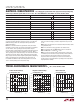
LT3757/LT3757A Typical Performance Characteristics Dynamic Quiescent Current vs Switching Frequency 35 TA = 25°C, unless otherwise noted. Normalized Switching Frequency vs FBX RT vs Switching Frequency 1000 CL = 3300pF 120 NORMALIZED FREQUENCY (%) 30 20 RT (kΩ) IQ(mA) 25 100 15 10 5 0 10 0 100 200 300 400 500 600 700 800 900 1000 SWITCHING FREQUENCY (KHz) 20 –0.4 0 0.4 0.8 FBX VOLTAGE (V) 1.2 1.
LT3757/LT3757A Typical Performance Characteristics INTVCC Minimum Output Current vs VIN INTVCC vs Temperature 90 TJ = 150°C 80 INTVCC CURRENT (mA) INTVCC (V) 7.3 7.2 7.1 INTVCC Load Regulation 7.3 VIN = 8V 7.2 70 INTVCC VOLTAGE (V) 7.4 TA = 25°C, unless otherwise noted. 60 50 INTVCC = 6V 40 INTVCC = 4.5V 30 20 7.1 7 6.9 10 7.0 –75 –50 –25 0 0 25 50 75 100 125 150 TEMPERATURE (°C) 0 5 10 3757 G13 15 20 25 VIN (V) 30 35 6.8 40 700 7.30 90 150°C 7.
LT3757/LT3757A Pin Functions VC (Pin 1): Error Amplifier Compensation Pin. Used to stabilize the voltage loop with an external RC network. FBX (Pin 2): Positive and Negative Feedback Pin. Receives the feedback voltage from the external resistor divider across the output. Also modulates the frequency during start-up and fault conditions when FBX is close to GND. SS (Pin 3): Soft-Start Pin. This pin modulates compensation pin voltage (VC ) clamp. The soft-start interval is set with an external capacitor.
LT3757/LT3757A Block Diagram CDC L1 R4 + R3 D1 VOUT • VIN CIN L2 • 9 IS1 2µA 2.5V 2.5V IS3 IS2 10µA VC 1 CC2 A10 CC1 1.72V –0.88V – + – + A12 G6 VC FBX 2 –0.8V D2 7.2V LDO INTVCC 8 + – DRIVER – +A7 G5 R S GATE G2 O VISENSE RAMP GENERATOR – +A3 G1 + + – D3 SS – + + A5 – 108mV SENSE 6 GND RSENSE 100kHz-1MHz OSCILLATOR A4 Q1 FREQ PROG RT SYNC 5 CSS M1 11 1.25V FREQ FOLDBACK 3 7 PWM COMPARATOR RAMP 1.25V CVCC 2.7V UP 2.
LT3757/LT3757A Applications Information Main Control Loop The LT3757 uses a fixed frequency, current mode control scheme to provide excellent line and load regulation. Operation can be best understood by referring to the Block Diagram in Figure 1. The start of each oscillator cycle sets the SR latch (SR1) and turns on the external power MOSFET switch M1 through driver G2. The switch current flows through the external current sensing resistor RSENSE and generates a voltage proportional to the switch current.
LT3757/LT3757A Applications Information INTVCC Regulator Bypassing and Operation An internal, low dropout (LDO) voltage regulator produces the 7.2V INTVCC supply which powers the gate driver, as shown in Figure 1. If a low input voltage operation is expected (e.g., supplying power from a lithium-ion battery or a 3.3V logic supply), low threshold MOSFETs should be used. The LT3757 contains an undervoltage lockout comparator A8 and an overvoltage lockout comparator A9 for the INTVCC supply.
LT3757/LT3757A Applications Information Prior to lowering the operating frequency, however, be sure to check with power MOSFET manufacturers for their most recent low QG, low RDS(ON) devices. Power MOSFET manufacturing technologies are continually improving, with newer and better performance devices being introduced almost yearly.
LT3757/LT3757A Applications Information Duty Cycle Consideration Soft-Start Switching duty cycle is a key variable defining converter operation. As such, its limits must be considered. Minimum on-time is the smallest time duration that the LT3757 is capable of turning on the power MOSFET. This time is generally about 220ns (typical) (see Minimum On-Time in the Electrical Characteristics table).
LT3757/LT3757A Applications Information FBX Frequency Foldback When VOUT is very low during start-up or a short-circuit fault on the output, the switching regulator must operate at low duty cycles to maintain the power switch current within the current limit range, since the inductor current decay rate is very low during switch off time. The minimum on-time limitation may prevent the switcher from attaining a sufficiently low duty cycle at the programmed switching frequency.
LT3757/LT3757A Applications Information Due to the current limit function of the SENSE pin, RSENSE should be selected to guarantee that the peak current sense voltage VSENSE(PEAK) during steady state normal operation is lower than the SENSE current limit threshold (see the Electrical Characteristics table). Given a 20% margin, VSENSE(PEAK) is set to be 80mV. Then, the maximum switch ripple current percentage can be calculated using the following equation: c= ∆VSENSE 80mV − 0.
LT3757/LT3757A Applications Information Boost Converter: Inductor and Sense Resistor Selection For the boost topology, the maximum average inductor current is: 1 IL(MAX) =IO(MAX) • 1− DMAX RSENSE = Then, the ripple current can be calculated by: ∆IL = c •IL(MAX) = c •IO(MAX) • 1 1− DMAX The constant c in the preceding equation represents the percentage peak-to-peak ripple current in the inductor, relative to IL(MAX). The inductor ripple current has a direct effect on the choice of the inductor value.
LT3757/LT3757A Applications Information Boost Converter: Output Diode Selection To maximize efficiency, a fast switching diode with low forward drop and low reverse leakage is desirable. The peak reverse voltage that the diode must withstand is equal to the regulator output voltage plus any additional ringing across its anode-to-cathode during the on-time.
LT3757/LT3757A Applications Information For the bulk C component, which also contributes 1% to the total ripple: COUT ≥ IO(MAX) 0.01• VOUT • f The output capacitor in a boost regulator experiences high RMS ripple currents, as shown in Figure 6. The RMS ripple current rating of the output capacitor can be determined using the following equation: IRMS(COUT) ≥IO(MAX) • DMAX 1− DMAX Multiple capacitors are often paralleled to meet ESR requirements.
LT3757/LT3757A Applications Information Flyback Converter: Switch Duty Cycle and Turns Ratio The flyback converter conversion ratio in the continuous mode operation is: VOUT NS D = • VIN NP 1− D where NS/NP is the second to primary turns ratio. Figure 8 shows the waveforms of the flyback converter in discontinuous mode operation. During each switching period TS, three subintervals occur: DTS, D2TS, D3TS. During DTS, M is on, and D is reverse-biased. During D2TS, M is off, and LS is conducting current.
LT3757/LT3757A Applications Information Flyback Converter: Transformer Design for Discontinuous Mode Operation The transformer design for discontinuous mode of operation is chosen as presented here. According to Figure 8, the minimum D3 (D3MIN) occurs when the converter has the minimum VIN and the maximum output power (POUT).
LT3757/LT3757A Applications Information where VSN is the snubber capacitor voltage. A smaller VSN results in a larger snubber loss. A reasonable VSN is 2 to 2.5 times of: VOUT • NP NS LLK is the leakage inductance of the primary winding, which is usually specified in the transformer characteristics. LLK can be obtained by measuring the primary inductance with the secondary windings shorted.
LT3757/LT3757A Applications Information Flyback Converter: Output Diode Selection Flyback Converter: Input Capacitor Selection The output diode in a flyback converter is subject to large RMS current and peak reverse voltage stresses. A fast switching diode with a low forward drop and a low reverse leakage is desired. Schottky diodes are recommended if the output voltage is below 100V. The input capacitor in a flyback converter is subject to a large RMS current due to the discontinuous primary current.
LT3757/LT3757A Applications Information SEPIC Converter: Switch Duty Cycle and Frequency For a SEPIC converter operating in CCM, the duty cycle of the main switch can be calculated based on the output voltage (VOUT), the input voltage (VIN) and the diode forward voltage (VD).
LT3757/LT3757A Applications Information Given an operating input voltage range, and having chosen the operating frequency and ripple current in the inductor, the inductor value (L1 and L2 are independent) of the SEPIC converter can be determined using the following equation: L1= L2 = VIN(MIN) 0.5 • ∆ISW • f • DMAX For most SEPIC applications, the equal inductor values will fall in the range of 1µH to 100µH.
LT3757/LT3757A Applications Information SEPIC Converter: Output Diode Selection To maximize efficiency, a fast switching diode with a low forward drop and low reverse leakage is desirable. The average forward current in normal operation is equal to the output current, and the peak current is equal to: 1 c ID(PEAK) = 1+ •IO(MAX) • 2 1− DMAX CDC has nearly a rectangular current waveform. During the switch off-time, the current through CDC is IIN, while approximately –IO flows during the on-time.
LT3757/LT3757A Applications Information Inverting Converter: Switch Duty Cycle and Frequency For an inverting converter operating in CCM, the duty cycle of the main switch can be calculated based on the negative output voltage (VOUT) and the input voltage (VIN).
LT3757/LT3757A Applications Information should be kept as tight as possible to reduce inductive ringing: Board Layout The high speed operation of the LT3757 demands careful attention to board layout and component placement. The Exposed Pad of the package is the only GND terminal of the IC, and is important for thermal management of the IC. Therefore, it is crucial to achieve a good electrical and thermal contact between the Exposed Pad and the ground plane of the board.
LT3757/LT3757A Applications Information Check the stress on the power MOSFET by measuring its drain-to-source voltage directly across the device terminals (reference the ground of a single scope probe directly to the source pad on the PC board). Beware of inductive ringing, which can exceed the maximum specified voltage rating of the MOSFET. If this ringing cannot be avoided, and exceeds the maximum rating of the device, either choose a higher voltage device or specify an avalancherated power MOSFET.
LT3757/LT3757A Typical Applications 3.3V Input, 5V/10A Output Boost Converter L1 0.5µH CIN 22µF 6.3V ×2 Efficiency vs Output Current VIN INTVCC 49.9k CVCC 4.7µF 10V X5R SHDN/UVLO 34k LT3757 GATE SYNC SS 41.2k 300kHz D1 M1 FBX RT 100 34k 1% 22Ω SENSE VOUT 5V 10A + COUT1 150µF 6.3V ×4 GND VC 0.004Ω 1W 6.8k 0.
LT3757/LT3757A Typical Applications 8V to 16V Input, 24V/2A Output Boost Converter VIN 8V TO 16V CIN 10µF 25V X5R R3 200k L1 10µH VIN SHDN/UVLO R4 43.2k D1 LT3757 SYNC GATE M1 R2 226k 1% SENSE RT SS VC RT 41.2k 300kHz CC2 100pF GND FBX INTVCC RC 22k CSS 0.1µF VOUT 24V 2A CC1 6.8nF CVCC 4.7µF 10V X5R RS 0.01Ω 1W CIN, COUT2: MURATA GRM31CR61E106KA12 COUT1: KEMET T495X476K035AS D1: ON SEMI MBRS340T3G L1: VISHAY SILICONIX IHLP-5050FD-01 10µH M1: VISHAY SILICONIX Si4840BDP R1 16.
LT3757/LT3757A Typical Applications High Voltage Flyback Power Supply DANGER! HIGH VOLTAGE OPERATION BY HIGH VOLTAGE TRAINED PERSONNEL ONLY VIN 5V TO 12V T1 1:10 CIN 47µF 16V ×4 • 105k SHDN/UVLO 46.4k VIN INTVCC SYNC LT3757 22Ω CVCC 47µF 25V X5R 140k 100kHz GND VSW M1 1.50M 1% 1M 1% COUT 68nF ×2 22Ω SENSE FBX 10nF 6.8k 0.1µF VOUT 350V 10mA 1M 1% 220pF GATE RT SS VC • D1 0.02Ω 16.
LT3757/LT3757A Typical Applications 5.5V to 36V Input, 12V/2A Output SEPIC Converter VIN 5.5V TO 36V CIN1 4.7µF 50V ×2 CIN2 4.7µF 50V ×2 + 105k VIN L1A • IL1A SHDN/UVLO 46.4k SYNC LT3757A CDC 4.7µF 50V, X5R, ×2 GATE M1 IL1B SENSE RT SS 10k 6.8nF 0.1µF VOUT 12V 2A L1B • 0.01Ω 1W FBX GND INTVCC VC 41.2k 300kHz D1 VSW 105k 1% + 4.7µF 10V X5R COUT1 47µF 20V ×4 COUT2 10µF 25V X5R 15.
LT3757/LT3757A Typical Applications 5V to 12V Input, ±12V/0.4A Output SEPIC Converter VIN 5V TO 12V + CIN2 47µF 16V CIN1 1µF 16V, X5R 105k • VIN SHDN/UVLO 46.4k LT3757 SYNC T1 1,2,3,4 CDC1 4.7µF 16V, X5R M1 GATE CDC2 4.7µF 16V X5R SENSE RT FBX D1 5 0.02Ω COUT2 4.7µF 16V, X5R ×3 D2 GND INTVCC 6 • 30.9k 400kHz COUT2 4.7µF 16V, X5R ×3 158Ω 1% • SS VC 1.05k 1% 22k 0.1µF 100pF CVCC 4.7µF 10V X5R 6.8nF VOUT1 12V 0.4A GND VOUT2 –12V 0.
LT3757/LT3757A Package Description DD Package 10-Lead Plastic DFN (3mm × 3mm) (Reference LTC DWG # 05-08-1699 Rev C) 0.70 ±0.05 3.55 ±0.05 1.65 ±0.05 2.15 ±0.05 (2 SIDES) PACKAGE OUTLINE 0.25 ± 0.05 0.50 BSC 2.38 ±0.05 (2 SIDES) RECOMMENDED SOLDER PAD PITCH AND DIMENSIONS 3.00 ±0.10 (4 SIDES) R = 0.125 TYP 6 0.40 ± 0.10 10 1.65 ± 0.10 (2 SIDES) PIN 1 NOTCH R = 0.20 OR 0.35 × 45° CHAMFER PIN 1 TOP MARK (SEE NOTE 6) 0.200 REF 0.75 ±0.05 0.00 – 0.05 5 1 (DD) DFN REV C 0310 0.25 ± 0.05 0.
LT3757/LT3757A Package Description MSE Package 10-Lead Plastic MSOP, Exposed Die Pad (Reference LTC DWG # 05-08-1664 Rev H) BOTTOM VIEW OF EXPOSED PAD OPTION 1.88 ±0.102 (.074 ±.004) 5.23 (.206) MIN 1 0.889 ±0.127 (.035 ±.005) 1.68 ±0.102 (.066 ±.004) 0.05 REF 10 0.305 ± 0.038 (.0120 ±.0015) TYP RECOMMENDED SOLDER PAD LAYOUT 3.00 ±0.102 (.118 ±.004) (NOTE 3) DETAIL “B” CORNER TAIL IS PART OF DETAIL “B” THE LEADFRAME FEATURE.
LT3757/LT3757A Revision History (Revision history begins at Rev B) REV DATE DESCRIPTION PAGE NUMBER B 3/10 Deleted Bullet from Features and Last Line of Description Updated Entire Page to Add H-Grade and Military Grade Updated Electrical Characteristics Notes and Typical Performance Characteristics for H-Grade and Military Grade C D 5/11 07/12 1 2 4 to 6 Revised TA04a and Replaced TA04c in Typical Applications 30 Updated Related Parts 36 Revised MP-grade temperature range in Absolute Maxim
LT3757/LT3757A Typical Application High Efficiency Inverting Power Supply Efficiency vs Output Current R2 105k VIN L1 SHDN/UVLO R1 46.4k LT3757 SYNC GATE M1 Si7848BDP SENSE RT SS VC 41.2k 300kHz GND 9.1k 0.1µF CDC 47µF 25V, X5R • 100 L2 10nF 0.006Ω 1W FBX INTVCC CVCC 4.7µF 10V X5R 90 VOUT –5V 3A to 5A 84.5k D1 MBRD835L 16k L1, L2: COILTRONICS DRQ127-3R3 (*COUPLED INDUCTORS) 80 EFFICIENCY (%) CIN 47µF 16V X5R • VIN 5V TO 15V COUT 100µF 6.