
Datasheet

LT3970 Series
14
3970fc
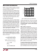
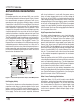
If the input voltage is ramped slowly, the boost capacitor
may not be fully charged. Because the boost capacitor is
charged with the energy stored in the inductor, the circuit
will rely on some minimum load current to get the boost
circuit running properly. This minimum load will depend
on input and output voltages, and on the arrangement of
the boost circuit. The minimum load generally goes to
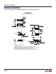
zero once the circuit has started. Figure 5 shows a plot
of minimum load to start and to run as a function of input
voltage. In many cases the discharged output capacitor
will present a load to the switcher, which will allow it to
start. The plots show the worst-case situation where V
IN
is ramping very slowly. For lower start-up voltage, the
boost diode can be tied to V
IN
; however, this restricts the
input range to one-half of the absolute maximum rating
of the BOOST pin.
Enable Pin
The LT3970 is in shutdown when the EN pin is low and
active when the pin is high. The rising threshold of the EN
comparator is 1V, with a 30mV hysteresis. This threshold
is accurate when V
IN
is above 4.2V. If V
IN
is lower than
4.2V, tie EN pin to GND to place the part in shutdown.
applicaTions inFormaTion
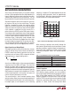
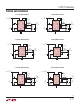
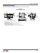
Figure 4. Two Circuits for Generating the Boost Voltage
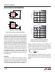
Figure 5. The Minimum Input Voltage Depends on
Output Voltage, Load Current and Boost Circuit
Adding a resistor divider from V
IN
to EN programs the
LT3970 to regulate the output only when V
IN
is above a
desired voltage (see Figure 6). This threshold voltage,
V
IN(EN)
, can be adjusted by setting the values R3 and R4
such that they satisfy the following equation:
V
IN(EN)
=
R3+ R4
R4
• 1V
where output regulation should not start until V
IN
is above
V
IN(EN)
. Note that due to the comparator’s hysteresis,
regulation will not stop until the input falls slightly below
V
IN(EN)
.
BD
LT3970
(4a) For V
OUT
≥ 2.2V
BOOSTV
IN
V
IN
C3
V
OUT
SW
GND
BD
LT3970
(4b) For V
OUT
< 2.2V; V
IN
< 27V
BOOSTV
IN
V
IN
C3
3970 F04
V
OUT
SW
GND
LOAD CURRENT (mA)
0 50
2.5
INPUT VOLTAGE (V)
3.5
5.0
100
200
250
3.0
4.5
4.0
150
300
350
FRONT PAGE APPLICATION
V
OUT
= 3.3V
TO START/RUN
LOAD CURRENT (mA)
0 50
4.0
INPUT VOLTAGE (V)
5.0
6.5
100
200
250
3970 F05
4.5
6.0
5.5
150
300
350
FRONT PAGE APPLICATION
V
OUT
= 5V
TO START
TO RUN